EC-99 BRAKE AND TRAIN AIR SIGNAL INSTRUCTIONS
March 1969
Click on the image for a full sized Cover
March 1969
Click on the image for a full sized Cover
NOTICE
The instructions set forth herein govern the
operation and maintenance of air brake and train
air signal equipment on the Penn Central Company,
and must be observed by all employes whose duties
are in any way affected thereby. They supersede
all previous rules and instructions inconsistent
therewith.
Employes required to be examined on the air
brake subject as prescribed in the several Air
Brake Examination Question and Answer Books
must attend air brake instruction classes once each
two years or as required by proper authority.
Failure to comply with this provision will result
in re-examination as prescribed in the examina-
tion books.
Each employee must have available a copy of
this book including all revisions while on duty and
when attending instruction classes.
Approved :
J. B. ADDINGTON
VICE PRESIDENT-OPERATION
EC-99 NOTICE PAGE (Revised 1-1-71)
CONTENTS
(Click on a page number to jump to it)
DEFINITIONS ........................................ 5
STANDARD AIR PRESSURE .............................. 12
1. Pressure Setting ................................ 12
la. Brake Pipe Equalization Pressure ............... 12
Ib. Freight Locomotives in Passenger Service ....... 13
INSPECTION AND MAINTENANCE OF LOCO-
MOTIVE AIR BRAKE AND SIGNAL EQUIPMENTS ............. 13
2. General ......................................... 13
2a. Inspection ..................................... 13
2b. Control of Pressure ............................ 15
2c. Piston Travel .................................. 15
ENGINEMAN'S RESPONSIBILITY ......................... 15
3. General ......................................... 15
3a. Inspection ..................................... 15
3b. Brake Tests .................................... 16
3c. Change of Engine Crew .......................... 17
OPERATION OF LOCOMOTIVE EQUIPMENT .................. 17
4. To Make a Pneumatic Service Application ......... 17
4a. To Release Train Brakes ........................ 18
4b. To Make an Emergency Application ............... 18
4c. To Release Brakes After Emergency Application .. 18
4d. To Apply or Release the Independent Brake ...... 18
4e. Dynamic Braking ................................ 19
SPEED CONTROL SYSTEM ............................... 20
6. Operation in Cab Signal Territory ............... 20
6a. Speed Limits ................................... 20
5b. Entering and Leaving Cab Signal Territory ...... 21
6c. Suppression of Speed Control Application ....... 21
6d. Recovery After Speed Control Application ....... 22
5e. Departure Test ................................. 22
5f. Speed Control or Cab Signal Failure ............ 23
AUTOMATIC TRAIN STOP M.U. CAR ..................... 23
6. General ......................................... 23
6a. Normal Operation with Train Stop ............... 24
6b. Operation with Cab Signals only—
Train Stop Cut Out ............................. 24
6c. Operation Without Cab Signal ................... 24
6d. Movement in Train without
Main Reservoir Pressure ........................ 24
6e. Test of Train Stop Equipment ................... 24
I
INTERMITTENT INDUCTIVE AUTOMATIC
TRAIN STOP .............................. 25
7. General .............................. 25
7a. Operation GRS Equipment ............. 25
7b. OperationUS&S Equipment ............. 26
7c. Departure Tests ..................... 28
DOUBLE HEADING AND HELPING LOCOMOTIVES .. 29
8. General .............................. 29
MAKING UP TRAINS ........................ 30
9. Passenger ............................ 30
Freight Cars in a Passenger Train .... 30
9a. Freight ............................. 30
9b. Passenger Cars in a Freight Train ... 31
9c. Dead Locomotive in a Freight Train .. 32
9e. Charging a Train .................... 32
9f. Brake Pipe Leakage Test ............. 33
TRAIN AIR BRAKE AND SIGNAL SYSTEM TESTS . 33
10. Responsibility ...................... 33
lOa. Condensation ....................... 33
lOb. Notification of Completion of Test . 34
lOc. Signal for Brake Application ....... 34
lOd. Condition of Brakes ................ 34
lOe. Cars Not Equipped with Air Brakes .. 34
lOf. Inoperative Brakes ................. 34
lOg. Test of Communicating Signal System. 36
INITIAL TERMINAL TRAIN AIR BRAKE TESTS .. 36
11. Train Test Requirements ............. 36
11a. Charging and Inspection ............ 36
11b. Train Brake Test ................... 37
11c. Piston Travel ...................... 40
11d. Tests from Yard Plant .............. 40
TRANSFER TRAIN AND YARD TRAIN TESTS ..... 41
12. Movements Not Exceeding 20 Miles .... 41
12a. Movements Exceeding 20 Miles ....... 41
12b. Switching Operations Within a ......
Passenger Terminal ................. 41
TRAIN BRAKE TESTS AT OTHER THAN
INITIAL TERMINAL ........................ 41
13. Passenger Train-Road Train Brake Tests 41
13a. Freight Train-Road Train Brake Tets 42
II
INTERMEDIATE BRAKE TESTS................. 42
14. Intermediate 500 Mile Inspection .... 42
14a. Change of Locomotive, Cabin Car or
Cutting Off Consecutive Cars at Point
Other Than Initial Terminal ........ 43
14b. Adding a Solid Block of Cars to Train
at a Terminal....................... 43
14c. Adding Cars to Train at Point Other
Than Terminal ...................... 43
14d. Change of CrewNo Change of Consist.. 44
RUNNING TESTS ........................... 44
15a. Passenger Trains ................... 44
15b. Freight Trains ..................... 45
BRAKE RULES GENERAL ..................... 45
16. Failure to Maintain Required Pressure 45
16a. Cutting Off Cars or Locomotives From
Train .............................. 45
16b. Securing Train on Grades ........... 46
16c. Sticking Brakes .................... 46
16d. If Train Breaks in Two ............. 47
16e. Reporting Defects .................. 47
INBOUND BRAKE EQUIPMENT INSPECTION ...... 48
17. Inspection of Trains ................ 48
17a. Application of Brakes for Inspection 48
TRAIN HANDLING .......................... 48
18. General ............................. 48
18a. Stopping Immediately After Starting . 49
18b. Stopping Trains Being Pushed ........ 49
18c. Starting Passenger Trains ........... 49
18d. Braking Passenger Trains ............ 50
18e. Starting Freight Trains ............. 52
18f. Braking Freight Trains .............. 53
18g. Dynamic Braking ..................... 56
18h. Smooth Handling ..................... 57
18i. Emergency Application, Accidental or
From Train .......................... 57
18j. To Apply Brakes from Train .......... 57
18k. Back Up Hose ........................ 58
181. Caboose Valves ...................... 59
18m. Failure of Locomotive Brakes ........ 59
18n. Brake Pipe Flow Indicator ........... 60
18o. Retaining Valves .................... 61
TRAIN AIR SIGNAL ......................... 61
19. Transmitting Signals ................ 61
19a. Inoperative Equipment ............... 62
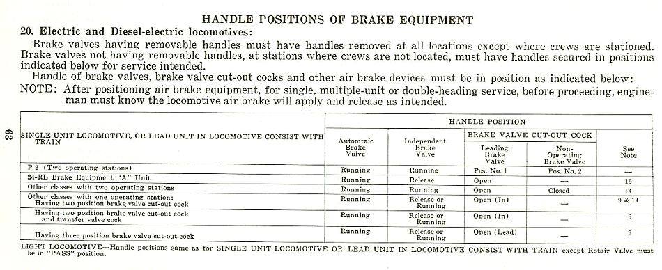
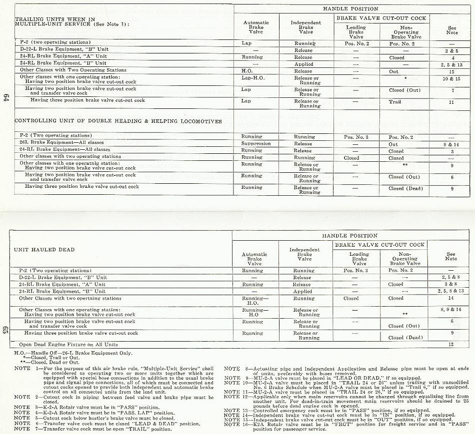
HANDLE POSITIONS OF BRAKE EQUIPMENT ...... 63
20. Electric and Diesel-Electric
Locomotives .......................... 63
III
DEFINITIONS
AFTER COOLER. Radiating piping which cools
the compressed air before it flows to the brake
system.
AIR BRAKE. A combination of parts operated by
compressed air and controlled manually or pneu-
matically, the use of which will retard or stop the
motion of a car or locomotive.
AIR COMPRESSOR. A device for compressing
air.
AIR GAUGE. An instrument which indicates the
amount of air pressure.
ALERTOR. A device which detects frequency of
movement of the engineman and initiates an air
brake application when the required frequency of
such movement is not maintained.
AUTOMATIC BRAKE VALVE. A manually oper-
ated device positioned by the engineman to (1)
control the flow of air into the equalizing reservoir
and brake pipe for charging and releasing a brake
application, and (2) provide a reduction of equal-
izing reservoir and brake pipe pressure at a service
or emergency rate.
AUTOMATIC DRAIN VALVE. A device which
automatically drains condensation from the air
brake system.
AUTOMATIC SLACK ADJUSTER. A device to
maintain brake cylinder piston travel within a pre-
determined range.
AUTOMATIC TRAIN STOP—MU CARS. A sys-
tem which produces a penalty application of the
brakes on the failure to acknowledge a change of
signal indication to a more restrictive indication.
AUTOMATIC TRAIN STOP—INTERMITTENT
INDUCTIVE—OTHER THAN MU CARS. A sys-
tem actuated by wayside inductor so arranged
that its operation will automatically result in the
application of the brakes until the train has been
brought to a stop.
BACK UP HOSE. A device consisting of a manual-
ly operated valve with a warning whistle, length
of hose and standard brake pipe hose coupling.
When properly coupled to the brake pipe hose on
" the leading end of a car or cars being pushed, pro-
vides the means of sounding a warning whistle or
5
applying the brakes either in service or emer-
gency.
BRAKE APPLICATION, (AUTOMATIC). A re-
duction of brake pipe pressure of sufficient amount
to cause the control valve, distributing valve or
triple valve to move to service or emergency posi-
tion, which, if made in the service position (or
zone) of the automatic brake valve, may consist
of one or more reductions. A BRAKE APPLICA-
TION IS NOT COMPLETED UNTIL BRAKE
PIPE EXHAUST HAS STOPPED COMPLETELY.
BRAKE CYLINDER. A cylinder in which com-
pressed air acts on a piston which transmits the
force of the compressed air to the associated brake
rigging.
BRAKE CYLINDER PRESSURE LIMITING
VALVE. A feature built into the 26-F and 26-C
control valves which limits service brake cylinder
pressure to a predetermined amount.
BRAKE CYLINDER RELEASE VALVE. A
manually operated valve on freight brake equip-
ment which permits the brake cylinder to be
drained without draining the reservoirs.
BRAKE PIPE. The system of piping including
branch pipes, angle cocks, cut-out cocks, dirt col-
lectors, hose and hose couplings, used for connect-
ing locomotive and all cars for the passage of air
to control the locomotive and car brakes.
BRAKE PIPE VENT VALVE. A device con-
nected to the brake pipe which propagates emer-
gency brake pipe reductions by venting the brake
pipe pressure locally.
BRAKE SYSTEM. Includes all brake apparatus,
such as air and electro-pneumatic brake, and re-
lated piping, hand brake, foundation brake rig-
ging and dynamic brake.
BRAKE VALVE CUT OUT COCK. A device
which provides the means to cut the automatic
brake valve in or out.
CABOOSE VALVE. A manually operated valve
located in cabin cars for applying, when neces-
sary, the train brakes either in service or emer-
gency.
CHARGING CUTOFF PILOT VALVE. Used
with 26 type locomotive equipment to provide the
following features during a break in two or a
train initiated emergency: Automatic sanding,
Dynamic brake cut out and Brake pipe cut off. In
6
order to reset this device after it has operated, the
26-C automatic brake valve must be placed into
emergency position and remain there for approxi-
mately one minute.
CHECK VALVE. A device so designed that it
permits air to flow in one direction while prevent-
ing the air from flowing in the opposite direction.
CLASP BRAKE. An arrangement of brake rig-
ging in which two brake shoes are used to clasp
the braking surface.
COMPRESSOR GOVERNOR. A device to auto-
matically control the operation of an air compres-
sor.
CONDUCTORS VALVE. A device on all passen-
ger carrying cars for applying the brakes from
the train (emergency application) when neces-
sary.
CONTROL VALVE. A device on locomotive or
cars which charges the reservoirs and moves to
apply and release the brake cylinder pressure in
response to the reduction or increase of brake
pipe pressure.
DEAD ENGINE FEATURE. A manually posi-
tioned device for charging the main reservoirs
from the brake pipe on a locomotive when main
reservoir pressure is not available.
DEADMAN FOOT VALVE. A device which will
apply the brakes on the locomotive and train af-
ter a short time delay, if foot pedal is released on
locomotive when brake cylinder pressure has not
previously been permitted to build up to at least
25 Ibs.
DECELOSTAT or ROLOKRON. A system that
automatically releases brake cylinder pressure
rapidly upon detection of wheel slide and restores
brake cylinder pressure as soon as wheel begins
to revolve.
DISC BRAKES. An arrangement of brake cylin-
ders and levers which force brake shoes against a
disc fastened to the wheel.
DISTRIBUTING VALVE. A device which applies
and releases the brakes on a locomotive and auto-
matically maintains the pressure in the brake cyl-
inder after a brake application.
7
DOUBLE CHECK VALVE. One having two
seats so arranged that air flowing past either seat
cannot flow out past the other seat but will flow
through a third common delivery connection.
DUPLEX RELEASE VALVE. An appliance per-
mitting manual reduction or depletion of auxilia-
ry reservoir pressure alone, or auxiliary and
emergency reservoir pressures together.
DYNAMIC BRAKING. A means of using the
traction motors to cause a braking effect.
EMERGENCY APPLICATION. A rate of brake
pipe reduction fast enough to cause the control
valves to move to emergency position.
EMERGENCY VALVE. A valve for the purpose
of applying the brakes in emergency.
FEED VALVE OR REGULATING VALVE. A
device which controls the pressure in the brake
pipe and maintains it at a predetermined setting.
FIRST SERVICE. (24-RL Locomotive equip-
ment). This position of the automatic brake valve
will produce an initial light brake pipe reduction
at a service rate followed by continuous controlled
slow rate of brake pipe reduction.
F-l SELECTOR VALVE. A device which auto-
matically arranges the brake equipment on the
locomotive to lead or trail other types of brake
equipment as directed by the MU-2A valve.
FULL SERVICE REDUCTION. A service brake
pipe reduction of sufficient amount to result in
equalization between brake cylinder pressure and
auxiliary reservoir pressure. (See Inst. la.)
GRADIENT, BRAKE PIPE. The difference in
brake pipe pressure between the front and the
rear of the train.
INDEPENDENT BRAKE VALVE. A device to
operate the air brakes on the locomotive indepen-
dently of the train brakes.
INTERCOOLER. Radiating piping which cools
the compressed air between stages of compres-
sion.
INTERMITTENT INDUCTIVE AUTOMATIC
TRAIN STOP. A device which produces a penalty
full-service brake application on failure to ac-
8
knowledge a signal indication other than clear,
limited clear and medium clear.
LOCOMOTIVE. A unit propelled by any form of
energy, or a combination of such units operated
from a single control station.
MAGNET VALVE. A valve for controlling the
flow of air, the operation of which is dependent
upon a magnet coil being energized or de-ener-
dized.
MAIN RESERVOIRS. One or more reservoirs on
a locomotive for storing the main supply of com-
pressed air.
MAIN RESERVOIR CUT OFF VALVE. A de-
vice to prevent the loss of main reservoir air.
MINIMUM REDUCTION (26-L Locomotive
Brake Equipment.) This position of the automa-
tic brake valve produces a limited service brake
pipe reduction.
MU-2A VALVE. A two or three position valve
which cuts out the independent brake valve on
trailing units. The three position MU-2A valve
also controls the F-l selector valve.
PRESSURE MAINTAINING. A feature of cer-
tain types of automatic brake valves which will
maintain brake pipe presure against maximum
permissible leakage during a service application.
PRESSURE RETAINING VALVE. A manually
positioned valve that will control the release of
brake cylinder pressure.
P-2-A BRAKE APPLICATION VALVE. A valve
which provides a full service brake application
when actuated by any one of the following fea-
tures: Overspeed control, Speed control, Alertor,
Deadman control, or Automatic Train Stop.
QUICK SERVICE VALVE. A device connected to
the brake pipe for the purpose of propagating
quick service by making a brake pipe reduction
on each car so equipped.
REDUCING VALVE. A valve to reduce main
reservoir pressure to a predetermined amount.
REDUCTION RELAY VALVE. A device com-
prising a quick service valve and a vent or emer-
gency valve mounted on a common pipe bracket.
9
It is connected to the brake pipe to provide addi-
tional local venting of brake pipe air on each car,
so equipped, during both service and emergency
brake applications. This device is auxiliary to the
control valve and utilized on cars having a great
amount of brake pipe volume.
RELAYAIR VALVE. A pneumatic device with a
spring loaded piston and valves so designed to
serve as a cut-off valve or relay valve upon move-
ment of the piston as a result of air flow from an-
other source; such as deadman, emergency brake
applications, etc.
RELAY VALVE. A valve used on locomotives
and cars which are equipped with more than one
brake cylinder. It relays the application and re-
lease operation of the distributing or control
valve and provides direct flow of main reservoir
air or supply reservoir air to the brake cylinders
under control of the distributing or control valve.
ROTAIR VALVE. A manually operated valve
which controls the rate of air pressure build-up in
brake cylinders of locomotive during emergency
brake application, also controls split or straight-
away full service applications in conjunction
with a penalty brake application. It also cuts in or
out the operation of the independent brake valve.
SAFETY VALVE. A valve designed to open and
close at predetermined pressure for which it has
been set. It is used to limit the maximum amount
of pressure in main reservoirs, compressor dis-
charge pipes (where used), control valves, dis-
tributing valves, brake cylinders and water rais-
ing systems.
SERVICE APPLICATION. A brake application
accomplished by making one or more brake pipe
reductions at a service rate.
SERVICE RATE OF REDUCTION. A reduction
of brake pipe pressure at a RATE fast enough to
cause the Control or Triple Valves to move to
Service position, but at a RATE not fast enough
to cause them to move to emergency position.
SIGNAL PIPE. A piping system including car
discharge valve, combined strainer and check
valve, cut out cocks, hose and hose couplings, that
runs the length of a passenger train and provides
the means of signaling engineman from any car
by use of the car discharge valve.
10
SIGNAL VALVE. A valve which operates to
cause the signal whistle to give audible sounds in
the locomotive cab.
SINGLE CAR EMERGENCY BRAKE. AC Mul-
tiple Unit (MU) cars used in single car operation
are equipped with the means of supplying main
reservoir pressure directly to the brake cylinders.
If the conventional air brake equipment should
fail, the Single Car Emergency brake can be ap-
plied by operating the EMERGENCY SWITCH
or VALVE in operating compartment.
SPEED CONTROL SYSTEM. A system which
provides a penalty application of the train brakes
on failure to acknowledge a change of Cab signal
indication to a more restrictive indication, or if
the speed permitted by the cab signal indication
is exceeded.
SUPPRESSION VALVE. A valve used with
train speed control to provide either a temporary
or permanent suppression of a penalty speed
control application.
TIMING VALVE. A valve used with Speed Con-
trol and Automatic Train Stop equipment to pro-
vide a six second warning whistle and delay time,
which if not acknowledged within the six second
delay time will produce a penalty brake applica-
tion.
TONS PER OPERATIVE BRAKE. The result of
dividing the gross tonnage of the train by the total
number of cars with operative brakes.
TONS PER EFFECTIVE GRADE BRAKE. The
result of dividing the gross tonnage of the train by
the number of effective retaining valves. An ef-
fective retaining value is one that will retain brake
cylinder pressure for a minimum of 3 minutes with
handle in either high or low pressure retain posi-
tion following an automatic brake application with
brake valve handle in release position.
TRIPLE OR CONTROL VALVES. Includes AB,
ABD, ABC, AB-1B, ABD-1B, D-22, D-24, UC and
26 type control valves and P or L triple valves
which charge the reservoirs, apply and release the
brakes on cars or locomotives.
UNDESIRED QUICK ACTION (UQA). An un-
desired emergency application of the brakes oc-
curring during a service brake application or
from other than a manual operation of the brake
equipment.
11
Click on the image for a full sized page 12
12
1b. Freight Locomotives in Passenger Service
When freight locomotives are used to haul passenger
trains, brake pipe pressure must be increased to standard
for passenger locomotives before locomotive is coupled to
train.
INSPECTION AND MAINTENANCE OF
LOCOMOTIVE AIR BRAKE AND
SIGNAL EQUIPMENT
2. General
Brake and air signal equipments on locomotive
units must be inspected and maintained in accord-
ance with current "Standard Maintenance Regu-
lations—Locomotives".
2-a. Inspection
Where mechanical forces are employed, before
a locomotive is dispatched for service, it must be
tested and it must be known that—
(1) Brakes are in a safe and suitable condition
for service.
(2) Air compressor or compressors are in condi-
tion to provide an ample supply of air for
service to which assigned and it must be
known that the crankcase contains a proper
amount of oil, that tlie compressor is
mounted securely, and that when operating,
it does not produce any undue vibration or
pounding.
(3) Accumulated water and oil have been
drained from the main reservoir system and
compressor intercoolers.
(4) Condensate is blown from end brake pipe
and main reservoir equalizing hose.
(5) MU hose are properly coupled between
units and on leading and trailing ends of
consist are either coupled to dummy coup-
lings or in receptacle provided for the hose.
(6) All angle cocks and cut-out cocks and por-
tions used to multiple various equipment
are in proper position as specified in In-
struction 20.
(7) Devices for regulating air pressures are
functioning properly and are adjusted to
prescribed pressures.
(8) Various cut-out cocks used in connection
with Deadman, Over-Speed, Train Speed
Control, Automatic Train Stop and Engine
13
Control Cut-out Cock are properly posi-
tioned and sealed. Seals will be applied to
enclosures where cut-out cocks are not read-
ily accessible for inspection. When any seal
is found to be broken, missing or tampered
with, it must be replaced before leaving en-
ginehouse territory.
(9) All safety devices are functioning properly
(10) Brake valves function properly in all posi-
tions.
(11) Brake pipe leakage must not exceed 3
pounds per minute, after a reduction of 10
pounds has been made from standard brake
pipe pressure. Pressure maintaining must
be cut out during this test.
(12) On locomotives equipped with Dynamic
brake, the Dynamic Interlock must be test-
ed as follows: With the locomotive brake
applied with Automatic Brake Valve, and
independent brake valve in Release posi-
tion, move Dynamic Brake Control to brak-
ing position. Locomotive air brake should
immediately release on all units. Move auto-
matic brake valve to Emergency position
and note that brake reapplies.
(13) Hand brakes, when equipped, are in a safe
and suitable condition for service.
(14) The communicating signal system on loco-
motives when used in passenger service is
in proper condition for service.
(15) Brake equpiment and safety supports,
where used, are in safe and suitable condi-
tion for service. No part of foundation
brake rigging and safety supports shall be
less than 2i/.j inches above rail.
(16) Brake levers, rods, brake beams, hangers
and pins, do not foul or bind in any way
that will affect proper operation of the
brakes.
(17) All pins are properly applied and secured in
place with suitable locking devices.
(18) Brake shoes are properly applied and ap-
proximately in line with tread of wheels or
other braking surfaces.
(19) Piston travel is properly adjusted.
14
2-b. Control of Pressure
Air compressor governors on electric or Diesel-
electric locomotives must operate to control main
reservoir pressure within 5 pounds above or below
the standard pressure, and when the operating or
loading cycle is initiated, the pressure must be
increased not less than 10 psi.
2-c. Piston Travel
Brake cylinder piston travel must be sufficient
to provide proper brake shoe clearance when the
brakes are released and with a full service brake
application must be adjusted within the following
limits
Inches
Electric Locomotives
Driver Brake .................. 4-6
Truck Brake (Except GG1) ...... 3-5
Truck Brake (GG1) ............. 4 1/2-5 1/2
Diesel Electric Locomotives
Double Acting truck mounted ... 2 1/2-3 1/2
Single Acting truck Mounted
(clasp) ..................... 3-5
Single Acting truck mounted
(single shoe) ............... 1-3
ENGINEMAN'S RESPONIBILITY
3. General
The engineman when taking charge of locomo-
tive must make the following inspection noting
that the equipment is properly positioned, as
specified in Section 3a, and responds properly to
the tests outlined in Section 3b. Where mechan-
ical forces are employed and on duty, the engine-
man will accept the inspection of the mechanical
forces for Section 3a and will be only required to
make brake tests as outlined in Section 3b.
3-a. Inspection
Prior to making the brake tests, it must be de-
termined that:
(1) MU hose are properly coupled between
units and on leading and trailing ends of
consist are either coupled to dummy coup-
lings or in receptable provided for the hose.
15
(2) All angle cocks and cut-out cocks and por-
tions used to multiple various equipment
are in proper position as specified in In-
struction 20.
(3) Brake valve cut-out cocks at all stations,
except the operating station, are in cutout
position.
(4) Various cutout cocks used in connection
with Deadman, Over-Speed, Speed Control
System, Automatic Train Stop System and
Engine Control Cut-out Cock, are properly
positioned and sealed. Seals will be applied
to enclosures where cutout cocks are not
readily accessible for inspection.
(5) Devices for regulating air pressures are
functioning properly and are adjusted to
prescribed pressures.
(6) Brake shoes are approximately in line with
tread of wheels.
(7) Hand brake released on all trailing units.
(8) At operating station—Brake Valve Cut-Out
Cock cut-in—handles inserted in Release or
Running position, Equalizing Reservoir,
Brake Pipe and Main Reservoir pressure—as
specified for locomotive type.
(9) Locomotive secured to prevent movement
during test.
(10) The communicating signal system on loco-
motives when used in passenger service
must be tested and known to be in a safe and
suitable condition for service before each
trip.
(11) Accumulated oil and water condensate is
drained from main reservoir system.
(12) Condensate is blown from end brake pipe
and main reservoir equalizing hoses.
3-b. Brake Tests
After the above inspection has been made, the
brakes must be tested from the operating station
to be used, and it must be determined that the
brakes on each unit of the locomotive consist re-
spond properly to the following:
(1) Application and Release—Independent
Brake Valve.
16
(2) Ten (10) pound Service Brake Pipe Reduc-
tion—Brake pipe leakage not to exceed
three (3) pounds per minute. Pressure
maintaining must be cut out during this
test.
(3) Release of service application—Dynamic
brake interlock.
(4) Nullify dynamic brake interlock—Automa-
tic brake valve emergency.
(5) Brake valve cutout cock will not allow brake
pipe pressure to increase—Brake valve cut-
out cock closed, automatic brake valve in
running. (Duration one (1) minute.)
(6) Deadman application—Deadman foot valve,
Alertor or other device for initiating dead-
man brake application.
(7) Quick release of service application—Inde-
pendent brake valve.
(8) Emergency application—Emergency brake
valve.
(9) To determine the brakes are applied or re-
leased on units, it must be observed that the
brake shoes are either against or away from
the wheels.
(10) Power Knockout should occur during tests
Nos. 4, 6,11,12 and 13.
(11) Speed Control—See instruction 5e.
(12) Automatic Train Stop—MU Cars—See in-
struction 6e.
(13) Automatic Train Stop—Intermittent In-
ductive—See instruction 7c.
3-c. Change of Crew
Enginemen taking charge of locomotive units
coupled to through trains with a direct change of
engine crews, will ascertain from incoming en-
gineman or from prescribed form made out by
him that locomotive brakes are in operative con-
dition. .
OPERATION OF LOCOMOTIVE EQUIPMENT
4. To make a Pneumatic Service Application
Move handle of automatic brake valve to Ser-
vice postion and hold there until equalizing res-
17
ervoir pressure, as indicated by equalizing res-
ervoir hand on the gauge, has been reduced de-
sired amount; then move handle to Lap position
(26-L self-lapping automatic brake valve automa-
tically laps).
4-a. To Release Train Brakes
Move handle of automatic brake valve to Run-
ning or Release position. If it is desired to keep
locomotive brakes applied while releasing train
brakes, (1) equipment having Lap position on the
independent brake valve, place handle of inde-
pendent brake valve in Lap position. (2) equip-
ment having a self-lapping independent brake
valve, place independent brake valve handle in
Application zone before moving automatic brake
valve handle to Running or Release position.
4-b. To Make an Emergency Application
Move automatic brake valve handle quickly to
Emergency position where it must remain until
train stops. Emergency application may also be
made by opening the emergency brake valve,
where provided.
4-c. To Release Brakes After Emergency
Application
Should emergency brake application occur
from any cause, after train has stopped, lap auto-
matic brake valve (emergency position with No.
26 brake valve) for one minute before attempting
to release. Refer to Instruction No. 4a for releas-
ing brakes.
4-d. To Apply or Release the Independent
Brake
On locomotives with self-lapping independent
brake valve, move independent brake valve handle
into Application zone. Release and Running po-
sition of the self-lapping independent brake valve
is with handle in extreme position to the left. As
handle is moved away from Release and Running
position it enters Application zone. The amount of
brake cylinder pressure developed is in propor-
tion to distance handle is moved into application
zone, and valve automatically laps to maintain a
constant pressure according to the position in
which its movement is stopped. The independent
brake valve is fully applied when handle is in
extreme position to the right. Quick Release posi-
tion is obtained by depressing independent brake
valve handle while positioned in Release and Run-
ning position. Locomotive brake should release
under any and all conditions when Quick Release
position is used.
18
On locomotives with other than self-lapping in-
dependent brake valves, to apply independent
brake, move handle of independent brake valve to
either Slow or Quick Application position as de-
sired. The Release position of independent brake
valve should release locomotive brake under any
and all conditions. Locomotive or locomotive units
operated in multiple unit operation afford control
of brakes on trailing units, from leading unit,
with independent brake valve, only when applica-
tion and release pipes and actuating or brake cyl-
inder equalizing pipes are connected properly be-
tween units.
With a multiple unit consist to assure a com-
plete release of all locomotive brakes with auto-
matic brake applied, the independent brake valve
handle must be held in Quick Release position un-
til brake cylinder pressure on leading unit has
been reduced to zero, then allow an additional 3
seconds for each unit in the consist.
With a multiple unit consist and automatic
brake applied, to reduce the locomotive brake ap-
plication on all units proceed as follows:
26 Brake Equipment
Move independent brake valve handle to de-
sired position in the Application zone then de-
press handle, holding it depressed until desired
brake cylinder pressure is obtained on the lea-
ing unit, then allow an additional 3 seconds for
each unit in the consist.
24RL Brake Equipment (Including GG1
Locomotives) and No. 6 Type Brake Equipment
Hold independent brake valve handle in Quick
Release Position until brake cylinder pressure on
leading unit has been reduced to zero, then allow
an additional 3 seconds for each unit in the con-
sist. Then make an independent brake application
to obtain desired amount of brake cylinder pres-
sure.
4-e. Dynamic Braking
On locomotives equipped with dynamic brake,
the automatic brake may be used when using dy-
namic braking as the dynamic interlock prevents
air brakes applying on the locomotive, however,
the independent brake must not be applied while
using dynamic brake as it may cause locomotive's
wheels to slide. When brakes are applied in emer-
gency the dynamic brake is automatically nullified
allowing a normal build-up of locomotive brake
cylinder pressure.
19
20
SPEED CONTROL SYSTEM
5. Operation in Cab Signal Territory
Locomotives equipped with speed Control must
have the equipment set up in the following man-
ner:
NOTE—When double heading or with multiple-
unit operation of electric or Diesel-electric loco-
motives, these instructions apply only to leading
locomotive or unit.
Speed Control switch must be in "Normal" posi-
tion. Locomotives having two sets of controls,
both Speed Control switches must be in "Normal"
position.
Speed Control cut-out cock must be sealed in
cut-in (OPEN) position. Locomotives on which
the deadman and overspeed devices utilize the
service application portion of the DS-24 automatic
brake valve, have a separate Speed Control cut-
out cock located in the piping adjacent to the
timing valve. Locomotives with DS-24 type auto-
matic brake valve but which do not use the service
application portion of the automatic brake valve
for control of deadman and overspeed devices,
utilize the cut-out cock on service application por-
tion of the automatic brake valve as the Speed
Control cut-out cock.
Changeover cock must be sealed in closed posi-
tion. Locomotives having two sets of controls usu-
ally have two changeover cocks, both of which
must be sealed in closed position. Changeover
cocks are located at the timing valves. With
changeover cock closed, the warning whistle will
sound, with diminishing intensity, for approxi-
mately six seconds, when actuated by a change to
a more restrictive indication, or by speed in excess
of that permitted by cab signal indication.
5-a. Speed Limits.
Speed Control imposes the following speed lim-
its, according to cab signal indication:
Car Signal Indication
Clear No Limit
Approach Medium 45 m.p.h.
Approach 30 m.p.h.
Restricting 20 m.p.h.
When cab signal changes to a less favorable in-
dication and speed is above that permitted by
governor setting, acknowledgment must be made
and manual brake suppression initiated before
six (6) seconds have elapsed in order to forestall
a Speed Control brake application. When speed
20
has been reduced to the limit imposed by cab sig-
nal indication, and the timing valve pressure has
been restored to at least 40 pounds the brakes may
be released.
5-b. Entering and Leaving Cab Signal
Territory.
The Speed Control Switch must be kept in its
"Normal" position at all times while on track
where Cab Signal rules are in effect for the direc-
tion the train is moving.
When leaving Cab signal territory or entering a
track on which cab signal rules are not in effect
for the direction the train is moving, the Speed
Control switch must be left in "Normal" position
unless or until, block signal or operating instruc-
tions permit a speed of more than 15 MPH. It
must then be moved immediately to the "Reverse"
position.
When entering a track on which Cab Signal rules
are in effect for the direction that the train is
moving this switch will be put in "Normal" posi-
tion at once.
Failure to place this switch in "Normal" posi-
tion within six (6) seconds after receiving other
than a restricting cab signal indication will re-
sult in a Speed Control application of the brakes.
Each change to a more restrictive cab signal indi-
cation willl cause the warning whistle to sound.
Failure to acknowledge change by operating the
acknowledging switch within six (6) seconds will
result in a Speed Control application of the brakes.
5-c. Suppression of Speed Control Application.
Sounding of the warning whistle, when loco-
motive speed is above the limit imposed by cab
signal indication, is a signal to reduce speed. Man-
ual brake suppression must be initiated before
six (6) seconds elapse.
Manual brake suppression is accomplished by
making a service brake pipe reduction, which may
be made with one or more reductions.
The suppression gauge will indicate pressure
while the automatic brake valve is in First Ser-
vice, Minimum Reduction or Service Zone and
will show a drop in pressure while the automatic
brake valve is in Lap position unless service brake
pipe reduction is sufficient to provide full suppres-
sion. Suppression gauge pressure must not be per-
mitted to drop below 20 pounds during the several
reductions of a split service reduction.
When suppression gauge pressure does not drop
when automatic brake valve is placed in Lap posi-
21
tion, after a service brake pipe reduction, full
manual brake suppression has been made.
In freight service the initial reduction must be
made in First Service or Minimum Reduction of
the automatic brake valve. After the service re-
duction has been made and speed reduced below
the limit imposed by cab signal indication, the
brakes may be released, providing the acknowledg-
ing switch has been operated. Timing valve air
gauge will indicate pressure if acknowledgment
has been made. Failure to acknowledge, failure to
make heavy enough service brake pipe reduction,
or attempting to release brakes before timing
valve pressure has been restored will cause a Speed
Control brake application.
5-d. Recovery After Speed Control Application.
When a Speed Control application occurs, the
automatic brake valve handle must be placed in
Lap or Suppression position. When application
pressure builds up to approximately 125 pounds,
the acknowledging switch must be operated and
when timing valve gauge indicates about 40
pounds pressure, the brakes can be released.
5-e. Departure Test.
Speed control equipment must be tested at same
time that cab signal test is made. When locomotive
has two operating positions, test must be made
from each position except, when operating several
locomotives or units in multiple-unit operation,
the leading and trailing operating positions only
need be tested.
To make departure test of Speed Control, the
equipment must be set up as provided in Instruc-
tion No. 5, then proceed as follows:
Acknowledge change of cab signal indication
from Clear to Approach Medium and from Ap-
proach Medium to Approach. On change from Ap-
proach to Restricting, do not acknowledge. Make
manual brake suppression as provided in Instruc-
tion No. 5c and lap brake valve. Speed Control
application should not occur. Observe that timing
valve gauge drops to zero, suppression gauge pres-
sure holds at suppression pressure, and applica-
tion gauge holds at main reservoir pressure. Then
still without acknowledging move brake valve han-
dle to Running position which will cause Speed
Control application. Observe that brake pipe pres-
sure continues to drop then lap brake valve and
when application pressure builds up to approxi-
mately 125 pounds (about 65 seconds) acknowl-
edge and when timing valve gauge pressure builds
up to about 40 pounds, brakes can be released.
22
5-f. Speed Control or Cab Signal Failure.
In case of failure of Speed Control equipment
or a cab signal failure which imposes a speed lim-
it under that permitted by "Rules for Conducting
Transportation" with a cab signal failure, the
seal on the Speed Control cut-out cock may be
broken and the cut-out cock moved to cut out
position. Report must be made and train operated
as prescribed by the Rules for Conducting Trans-
portation.
Locomotive must not be operated with cab sig-
nals and without Speed Control unless the seal
is broken on the changeover cock and cock placed
in open position. With changeover cock open, ac-
knowledging a change of cab signal to a more re-
strictive indication will silence the warning whis-
tle only if speed is below that called for by signal
indication. If overspeed, the whistle will sound
until speed is reduced.
AUTOMATIC TRAIN STOP—M.U. CARS
6. General
The Automatic Train Stop System is supple-
mental to, and augments, the existing cab signal
apparatus on these cars, so that when cab signal
changes to a less favorable indication, acknowl-
edgment must be made within six (6) seconds in
order to forestall an Automatic Train Stop appli-
cation which constitutes an automatic emergency
application of the brakes and removal of power
from the traction motors.
Once an automatic train stop application has
occurred, the brakes can only be released by first
moving the brake valve handle to LAP position or
SUPPRESSION position and letting it remain
there until the Train Stop Pilot Light goes out
after which the cab signal change must be ac-
knowledged. The brakes can then be released and
power applied in the usual manner.
An automatic train stop application cannot be
suppressed by any brake application.
Timing valve pressure as indicated by gauge
near Timing Valves should be set at 45 pounds.
When cab signal changes to a less favorable in-
dication the warning whistle will sound with dim-
inishing blast of approximately six (6) seconds
duration.
When taking control of car, as soon as control
plug is inserted in Master Controller, the cab sig-
nal acknowledging switch must be operated be-
fore moving brake valve handle from HANDLE
OFF or SUPPRESSION position.
23
The acknowledging switch must also be oper-
ated immediately upon insertion of Control Plug
following an overload re-setting manipulation.
6-a. Normal Operation with Train Stop
For normal operation with system cut in, the
two (2) cut-out cocks located underneath the floor
in vicinity of Timing Valve must be positioned
as follows:
1. Train Stop Cut-Out Cock sealed in OPEN
position. (Handle in line with pipe.)
2. Changeover Cock sealed in CLOSED posi-
tion. (Handle crosswise of pipe.)
6-b. Operation with Cab Signals only—Train
Stop Cut Out
For operation with cab signal, but without Au-
matic Train Stop, the two (2) cocks must be po-
sitioned as follows:
1. Train Stop Cut-Out Cock in CLOSED posi-
tion.
2. Changeover Cock in OPEN position.
6-c. Operation without Cab Signal
For operation without cab signal the Train
Stop Cut-Out Cock must be placed in "CLOSED"
position, and the Changeover Cock remain sealed
in "CLOSED" position.
6-d. Movement in Train without Main
Reservoir Pressure
When car is moved in train without main res-
ervoir pressure, the Train Stop Cut-Out Cock
should remain sealed in "OPEN" position, and
the Changeover Cock remain sealed in "CLOSED"
position.
6-e. Test of Train Stop Equipment
Test of the Train Stop Equipment must be made
whenever a standing test of the Cab Signals is
made, and shall be incorporated in the Cab Signal
Test as follows:
Make a 20 pound brake pipe reduction.
When the cab signal indication changes from
Clear to Approach Medium, and from Approach
Medium to Approach, acknowledgment should be
made promptly after the change in each instance.
On change from Approach to Restricting do not
acknowledge and note that an emergency brake
application occurs, and Train Stop Pilot Light is
24
lighted. Place automatic brake valve handle in
LAP or SUPPRESSION position until pilot light
is out. After pilot light is out—Acknowledge.
Brakes can then be released when desired.
AUTOMATIC TRAIN STOP
INTERMITTENT INDUCTIVE
7. General
These instructions apply only to the leading
locomotive or unit whether in single, multiple unit
or double heading operation in ATS territory.
7-a. Operation—GRS Equipment
1. Placing Apparatus in Service.
The following portion of instructions is based
on the locomotive being offered for service with
train control cut out.
(a) Place train control power switch in
"ON" position.
(b) Push reset button and hold for two sec-
onds (located outside on right side near
steps of locomotive). Train control
(TC) red light will go out.
(c) Train control electro-pneumatic (EP)
valve must be placed in "IN" position
and sealed.
(d) Engine control cutout cock must be in
"IN" position (90° to pipe) and sealed.
(Located near the EP cutout cock).
(e) Place automatic brake valve in Suppres-
sion position on 26L brake equipment
and in Lap position on all other type
brake equipment. The application valve
will reset and pneumatic control (PC)
light will go out.
(f) Return brake valve to Running or Release
position.
2. Acknowledging.
(a) Pull acknowledging handle back or
push acknowledging button.
(b) The handle and button are spring-
loaded and will return to their normal
positions when released.
(c) A timing mechanism is activated when
acknowledgment is made so that if han-
dle or button is held more than 15 sec-
onds the system is energized and an
automatic brake application will occur.
25
3. Forestalling Automatic Brake Application
When approaching wayside inductor at a sig-
nal requiring acknowledgment, pull the acknowl-
edging handle back or push button in advance of
passing over the inductor. The handle must be
kept back or button held down until the locomo-
tive receiver has passed over the inductor. Release
handle or button so that they can return to their
normal positions. A whistle or bell will sound
while acknowledging and passing over an induc-
tor.
4. Automatic Brake Application
Failure to take necessary action when passing
a signal requring acknowledgment will result in
a full service brake application with no warning
whistle or delay time. Train control red light and
PC light will come on. Holding acknowledging
handle back, or button in, more than the 15 sec-
onds allowed by the timing mechanism will also
cause an automatic brake application.
5. Recovery From Automatic Brake
Application
(a) Close throttle.
(b) Place automatic brake valve in Suppres-
sion position on 26L brake equipment
and in Lap position on all other type
brake equipment.
(c) When locomotive stops, push reset button
on outside of locomotive and hold for
two seconds. Train control and PC light
will go out.
(d) Return brake valve to Running or Re-
lease position.
6. Road Failure
(a) In event of an electrical or pneumatic
failure, break the seal on EP valve and
engine control cutout cock and close
both valves.
(b) Place train control power switch to
"OFF" position.
(c) Comply with C.T. 400, Rule 558.
(d) Make proper failure notation on En-
gineman's Work Report.
7-b. Operation—US&S Equipment
1. Placing Apparatus in Service
The following portion of instructions is based
on the locomotive being offered for service with
the cab signals not used.
26
(a) Place Cab Signal Power switch to "ON"
position (located on cab wall behind en-
gineman).
(b) Move acknowledging valve handle for-
ward to charge position "C" and after
four (4) or more seconds move handle
back to acknowledging position "A".
Whistle will blow during this function.
Valve is located on front of control
stand, below throttle.
(c) Open train stop cutout cock by position-
ing handle at 90 degrees to pipe and
seal. (Cutout cock is located in short
hood adjacent to train stop apparatus
on most units.)
Opening changeover cock before ac-
knowledgment is made will result in a
penalty application unless automatic
brake handle is in SUPPRESSION posi-
tion.
(d) Move acknowledging valve handle to
charge position "C".
2. Acknowledging
(a) Acknowledging valve handle should be
in charge position "C" long enough to
fill the acknowledging reservoir (four or
more seconds).
(b) Move handle from "C" to "A" position.
(c) Whistle will blow with a diminishing
blast until acknowledging reservoir is
depleted (about 25 seconds) or until
handle is returned to "C" position.
(d) Return handle to "C" position to re-
charge reservoir for next acknowledg-
ment.
3. Forestalling Automatic Brake Application
When approaching wayside inductor at a signal
requiring acknowledgment, the acknowledging
valve handle should be put in the "A" position in
advance of passing over the inductor. The handle
must be kept in the "A" position until the loco-
motive receiver has passed over the inductor. Re-
turn handle to 'C" position. A successful fore-
stalling is indicated by no brake application.
4. Automatic Brake Application
Failure to take necessary action when passing
a signal requiring acknowledgment will result in
a split-reduction, full service brake application
with no warning whistle or delay time.
27
5. Recovery From Automatic Brake
Application
(a) Move brake valve handle to SUPPRES-
SION position.
(b) In about 60 seconds, Application-air
gauge will move from minimum value
of approximately six pounds to 115-120
pounds, and application valve can be
heard resetting-. PC light will go out, on
units so equipped.
(c) Place acknowledging valve handle in
"A" position for four or more seconds,
then return to "C" position.
(d) Move brake valve handle to RE-
LEASE position. Failure to acknowl-
edge after application valve resets will
result in a penalty application when
brake valve handle is moved from
SUPPRESSION position.
6. Road Failure
(a) In event of an electric or pneumatic
failure, break the wire seal on train stop
cutout cock and move cock to cutout po-
sition (handle parallel with pipe).
(b) Throw cab Signal Power Switch to
"OFF" position.
(b) Comply with C.T. 400, Rule 558.
(d) Make proper failure notation on En-
gineman's Work Report.
7-c. Departure Tests
1. A test shall be made on each locomotive ei-
ther on departure from its initial terminal or if
apparatus is cut out, prior to entering equipped
territory. Only one departure test is required in
any 24-hour period. If a departure test is made
by an employe other than the engineman, Form
EL-104A shall be filled out and placed in the cab
for the engineman.
2. Before taking locomotive from terminal for
road service, engineman must:
(a) Note that cut-out cock at electro-pneu-
matic (EP) valve and engine run pres-
sure switch are sealed.
(b) Move locomotive over test inductor, at
not less than 2 miles per hour. .
(1) On units equipped with Gen-
eral Railway Signal Company
System:
With acknowledging lever
or push button held in full ac-
knowledging position, deter-
28
mine that the acknowledging
whistle or bell sounds when
passing over inductor and no
automatic train control brake
application occurs. If locomo-
tive is equipped with receiver
on each side, each receiver
must be checked.
(2) On units equipped with Union
Switch & Signal Company
System:
With acknowledging valve
handle moved to "A" position,
determine that acknowledging
whistle sounds and no train
control brake application oc-
curs, then return handle to "C"
position.
(c) Move locomotive over test inductor, at
not less than 2 miles per hour without
acknowledging, to determine that auto-
matic train control brake application
occurs. Reset train stop as outlined.
(d) If equipment fails to operate properly,
engineman must not take locomotive
from terminal unless instructed to do
so by proper authority.
DOUBLE HEADING AND HELPING
LOCOMOTIVES
8. General
When more than one locomotive is attached to
a train in double-heading or helper service, the
engineman on the leading locomotive in direction
of movement shall operate the train air brakes.
On all other motive power units in the train the
brake valve cut-out cock must be kept closed; the
standard main reservoir pressures maintained,
and all cocks and brake valve handles shall be
positioned as specified in Instruction 20.
In case it becomes necessary for the leading lo-
comotive to give up control of the train short of
destination of the train, a road test of the brakes
must be made to determine that the train air
brakes are operative from the automatic brake
valve of the locomotive taking control of the train.
Helping locomotives detached from the rear of
moving freight trains must be cut off in the fol-
lowing manner:
After the cut off signal has been given and has
been acknowledged, the angle cock or brake pipe
end cock on cabin car must be closed, coupler lock
on cabin car must be lifted which will permit
knuckle to open, leaving angle cock, end cock or
29
cut-out cock on locomotive open. The air hose be-
tween cabin car and locomotive must then be un-
coupled using the hose uncoupling device. When
hose is separated, the brakes on the helping loco-
motive will apply in emergency. Care must be ex-
ercised to see that hose is not permitted to pull
apart.
In case of emergency, the brakes can be applied
from a locomotive having the brake valve cut-out
cock closed, by moving the handle of the automat-
ic brake valve to emergency position (except on
No. 6 equipment) or by operating the emergency
valve.
MAKING UP TRAINS
9. Passenger
After properly connecting air hoses, open the
angle cock slowly and open signal line cut-out
cock. Always open the angle cock nearest the lo-
comotive first and the signal line cut-out cock
nearest the locomotive last. Then see that the cut-
out cock in the brake pipe branch pipe is open,
and that all hand brakes are released. If car is
equipped with a pressure retaining valve, it must
be in release position (handle pointing down-
ward).
The release feature on all passenger carrying
cars should be set for GRADUATED RELEASE.
The release feature on all mail, baggage and ex-
press cars should be set for DIRECT RELEASE.
The consist of a passenger train must not ex-
ceed 30 cars.
9-a. Freight Cars in a Passenger Train
Freight cars to be operated either permanently
or temporarily in passenger train service, the
brake cylinder or its pipe should be equipped with
a safety valve adjusted to open at approximately
60 pounds. Cars may be operated without this
safety valve and the engineman in charge of the
train notified. Engineman will operate the train
brakes under normal conditions in such a manner
as to avoid a service brake cylinder pressure in
excess of 60 pounds at speeds less than 25 miles
per hour.
9-b. Freight
After properly connecting air hose, open the
angle cock slowly and lock it. Open the angle cock
nearest the locomotive first. Then observe that cut-
out cock in branch pipe is open; that the hand
brakes are released and that the handle of the
pressure retaining valve is either in direct release
30
position or in a designated operating position
when so specified in Timetable Special Instruc-
tions.
Reducing valve for ground air lines used for
charging and testing air brakes of trains or cuts
of cars should be set for a maximum pressure of
70 pounds. Brake pipe feed valve of locomotives
in freight yard service should be set for 70 pounds.
When cars standing on charge are disconnected
from ground air line, before coupling locomotive
or other cars, a heavy service brake application
(at least full service) should be made by slowly
opening the angle cock.
Where yard locomotives make up and add cars
to the rear of a freight train, the brake pipe feed
valve of the locomotive should be reduced 10
pounds below standard pressure for that train be-
fore coupling the air into the cars to be added.
After coupling cars to the rear of the train and
stretching the portion of cars added, and before
any air hoses are coupled between the front and
rear portions of the train, the engineman of the
yard locomotive will make a full service brake pipe
reduction. When the brake application is com-
pleted and it has been noted that the brakes on the
added portion are applied, the trainman or car in-
spector will close the angle cock between the yard
locomotive and the added portion. The air hose
between the two portions of the train should then
be coupled and angle cocks opened slowly. The
road engineman will then proceed to make the
proper test of brakes.
9-c. Passenger Cars in a Freight Train
A passenger car when operated in a freight
train should be coupled as in the preceding para-
graphs but it must have the release feature set for
DIRECT RELEASE and the air supply to the wa-
ter raising system cut out if the train consists of
more than 30 cars. When cars are returned to pas-
senger service the release feature must be set for
GRADUATED RELEASE for all passenger carry-
ing cars and the air supply to the water raising
system cut-in.
The number of cars with passenger type brake
equipment must not exceed 20 in any train and
such cars must be located forward of the 40th
car. The total number of all cars in train shall
not exceed (a) 150 cars when handling 5 or less
passenger equipment cars; or (b) 100 cars when
handling more than 5 passenger equipment cars.
Passenger equipment cars having type AB-l-B
brake equipment may be handled in freight trains
without restriction. The signal line must not be
connected on such cars.
31
9-d. Dead Locomotives in a Freight Train
1) A dead locomotive in a freight train should
be coupled the same as a freight car. The
brake valve cut-out cock must be closed.
When main reservoir pressure is not avail-
able on the locomotive, the main reservoir
• must be charged from the brake pipe by
changing the "dead engine cap" or "cock"
to "DEAD" position, making certain that the
pressure in all main reservoirs is reduced to
at least 25 pounds before placing the cap or
cock in "DEAD" position. When the main
reservoir pressure is available on the unit
either from an associated unit or if compres-
sor is operating, it will not be necessary to
change the "dead engine cap" or "cock" to
"DEAD" position.
2) All auxiliary automatic brake applying de-
vices such as deadman, overspeed, etc., not
nullified by closing of brake valve cut-out
cock must be cut out individually. All air
operated devices except the brakes must be
cut out.
3) Locomotives and "B" units of Diesel-elec-
tric locomotives with controlled emergency
cock must have the cock in non-control or
"P" position.
4) Locomotives with 24RL brake equipment
and Rotair valve (s) must have the Rotair
valve (s) in passenger "P" position.
5) Locomotives with No. 26L brake equipment,
the MU-2A valve must be in "Lead or "Dead"
position. In the case where a double cut-
out cock is used in place of the MU-2A, the
cut-out cock must be in "In" position.
6) The handles of the automatic and indepen-
dent brake valves must either be removed, or
clamped in Running position.
7) The location of dead locomotives in a train
is specified in Rule 4161-A of Rules for Con-
ducting Transportation.
8) When a locomotive is moved "Dead" in train
and not associated in multiple with the haul-
ing locomotive consist, the brake cylinder
pressure must be limited to 30 Ibs. by adjust-
ment of safety valve on distributing valve
or on locomotive equipped with control valve
by installing safety valve in No. 16 pipe from
control valve.
9-e. Charging a Train
After coupling locomotive to train, the cou-
plers between the locomotive and train, and where
practicable, the entire train should be stretched
32
to see that all couplings are made. When this has
been determined the independent brake should be
applied. Before the brake pipe hose, between lo-
comotive and train, has been coupled, condensa-
tion must be blown from the brake pipe. Locomo-
tive brakes must remain applied while the train
is being charged.
To charge train use Release position of No. 24
or No. 26 brake valves and Running position of all
other types of brake valves.
During initial charging of a train, when neces-
sary, the output of the air compressor on diesel
locomotive may be increased by moving the
throttle to No. 4 or No. 5 position. Before opening
throttle the generator field switch must be in
"OFF" position and the reverse lever in "NEU-
TRAL" position. When main reservoir gauge in-
dicates normal cycling between CUT-IN and
CUT-OUT pressures, throttle should be reduced
to "IDLE" for the remainder of the charging
time.
9-f. Brake Pipe Leakage Test
After the air brake system on a train is suffi-
ciently charged to meet the requirements for the
particular type of train, make a 15 pound brake
pipe service reduction. After the brake pipe ex-
haust at the brake valve has completely stopped
blowing, wait an additional 30 seconds for brake
pipe pressure to settle throughout the train be-
fore starting to check the leakage, then check the
brake pipe leakage for one full minute as indi-
cated by the brake pipe gauge. Brake pipe leak-
age must not exceed 5 pounds per minute. On loco-
motives equipped with pressure maintaining fea-
ture, this feature must be cut out during test.
TRAIN AIR BRAKE AND
SIGNAL SYSTEM TEST
10. Responsibility
Supervisors are jointly responsible with inspec-
tors, enginemen and trainmen for condition of
air brake and communicating signal equipment on
locomotive and cars to the extent that it is possi-
ble to detect defective equipment by required air
tests.
10-a. Condensation
Condensation must be blown from the pipe from
which air is taken before connecting yard line
or motive power to train.
33
10-b. Notification of Completion of Test
When test of air brakes has been completed,
the engineman and conductor must be advised
that train is in proper condition to proceed, the
number of cars in train and the number having
operative brakes. In no case will a train be started
until the engineman and conductor are in posses-
sion of this information.
This information may be obtained from the em-
ployes who have personally inspected the train or
on prescribed form MP-261-C, properly filled out,
covering Report on Condition of Air Brakes. At
points specified in the Timetable Special Instruc-
tions this information may be received from the
Yardmaster or his representative.
Where the use of the above-mentioned form is
required on relay trains and enginemen are unable
to personally pass along the form, it will be the
responsibility of the Yardmaster or his designated
representative to obtain the form from the incom-
ing engineman and deliver it to the outgoing en-
gineman.
10-c. Signal for Brake Application
During standing tests, brakes must not be ap-
plied or released until proper signal is given.
10-d. Condition of Brakes
Each train must have the air brakes in effective
operating condition, and at no time shall the num-
ber of operative air brakes be less than 85% of
the total number of cars in train.
When piston travel is in excess of 10 inches the
air brakes cannot be considered in effective op-
erating condition.
10-e. Cars Not Equipped with Air Brakes
Any vehicle equipped with brake pipe only,
must be placed immediately ahead of the cabin
car and brakes cut in on the cabin car. Not more
than two such vehicles to be included in any train.
10-f. Inoperative Brakes
1) Freight cars on which the air brakes be-
come defective enroute may be hauled to the near-
est repair point, without change in the position
of the train provided 85 ''/c of the cars in train have
operative brakes. At the repair point the car with
defective brakes shall either be switched out or
repaired. When necessary to cut out brakes on
cars en route, care must be taken that no two
cars with brakes cut out are in consecutive order.
34
Maximum Number of
Cars with
Inoperative Brakes
0
1
2) Each locomotive unit except the leading unit
shall be counted as one car in determining per-
centage of operative brakes.
3) The following table shows the maximum
number of cars with inoperative brakes permitted
in a train in order to maintain no less than 85 %
with operative brakes:
Maximum Number of
Cars with
Number of Cars in Train Inoperative Brakes
6 cars or less ......................... 0
7 " to 13 cars, inclusive .............. 1
14 " " 19 " " ........................ 2
4) In case of emergency such as movement of live-
stock or perishable freight, a freight car with an operative
brake may be permitted to leave a terminal or pass a desig-
nated repair point, provided the movement is authorized by
the Superintendent and the car is places in the rear of all
cars having brakes operative, immediately ahead of caboose,
with brake pipe hose connected and angle coscks open. If
brake pipe on such car with inoperative brake is damaged,
car must be hauled to rear of caboose and properly secured
against separation.
Under no circumstances may the number of OPerative
brakes in the train be less than 85% of all cars in train.
(Revised 10-31-71)
Under no circumstances may the number of
operative brakes in the train be less than 85% of
all cars in train.
5) In case of failure of brake pipe or its con-
nections on a passenger car the signal line on the
defective car may be used to transmit the brake
pipe pressure to the rear cars by forcing the sig-
nal line hose coupling with the air brake hose
coupling on cars adjoining the one with the defec-
tive brake pipe,
This change will render inoperative the air sig-
nal on the defective car and all cars following.
The car discharge valve on the defective car must
be cut out. In order to obtain a signal from the
cars ahead of the defective one, the signal line
cut-out cock should be closed on the rear of the
car immediately ahead of the defective car. The
air brake must be cut out, brakes released and
reservoirs drained on the defective car. Before
proceeding, a road test of the brakes must be
made
Since the coupling of brake and signal hose
damages the couplings, all hoses which were
crossed under these conditions shall be removed
at the repair point and returned to reclamation
plant.
35
6) A passenger train must not be dispatched
from any terminal -with the air brake inoper-
ative on the rear car. Should air brake on rear car
become inoperative en route, report must be made
to the Superintendent at first point of communi-
cation, who will issue instructions.
7) A car having the hand brakes inoperative
must never be the rear car of a train.
8) Inoperative Air IBrafce on Loco-motives.
All locomotives must leave terminal points
with the air brakes in serviceable condition.
If a failure of locomotive brakes occurs en-
route, a report must be made, at the first
point of communication, to the Superinten-
dent who will issue instructions.
9) Inoperative Air Brake fiMi'TEaiiKs
Should the air brakes become inoperative
on a train it will proceed carefully, with
hand brakes when practicable, to the first
point of commuJiication where Conductor
will report to the Superintendent for In-
structions.
10-g. Test of Coimnnnricating Signal System
Communicating signal system on passenger
equipment trains must be tested and known to be
in a suitable condition for service before leaving
terminal.
INITIAL TERMINAL TRAIN
AIR BRAKE TESTS
11. Train Test Requirements
All trains must be given inspection and test as
specified by Instructions lla through lid at points
where:
a) Train is originally made up or .classified
(INITIAL TERMINAL).
b) Train consist is changed other than by add-
ing or removing a solid block of cars and
train brake system remains charged.
c) Train is received in interchange.
11-a. Charging and Inspection
An examination of the train brake system must
be made and it must be known that:
1) Train air brake system is charged to
required air pressure.
36
2) All air hose are coupled and in suit-
able condition for service.
3) Angle cocks, cut-out cocks and han-
dles of retaining valves are properly
positioned.
4) Reservoir drain cocks are closed.
5) Necessary repairs are made to reduce
leakage to a minimum.
6) Brake rigging does not bind or foul.
7) All parts of brake equipment are
properly secured.
8) Retaining valves and retaining valve
pipes are in condition for service.
9) Hand brakes are released unless re-
quired by grade.
10) If electro-pneumatic operation, brake
circuit cables are properly connected.
11-b. Train Brake Test
1) After the air brake system on a freight
train is charged to within 15 pounds of the set-
ting of the feed valve on the locomotive (not less
than 60 pounds with 70 pound feed valve setting)
as indicated by an accurate gauge at rear end of
train, and on a passenger train when charged to
not less than 90 pounds, and upon receiving the
signal to apply brakes for test, a 15 pound brake
pipe service reduction must be made in automatic
brake operation, the brake valve lapped, wait an
additional 30 seconds for brake pipe pressure to
settle throughout the train after brake pipe ex-
haust at brake valve has stopped, and the number
of pounds of brake pipe leakage per minute noted
as indicated by brake pipe gauge, after which
brake pipe reduction must be increased to full
service. Brake pipe leakage must not exceed 5
pounds per minute.
Inspection of train brakes must be made to de-
termine that angle cocks are properly positioned,
that the brakes are applied on each car and loco-
motive unit, that piston travel is correct, that
brake rigging does not bind or foul, and that all
parts of brake equipment are properly secured.
When this inspection has been completed, release
signal must be given and brakes released, and
each brake inspected to see that all have properly
released.
When the locomotive used to haul the train is
provided with means for maintaining brake pipe
pressure at a constant level during service appli-
cation of the train brakes, this feature must be
cut out during train air brake tests.
37
With 26L brake equipment the test will be
made as follows:
With the system properly charged as specified
above and the brake valve cut-off valve in "IN"
position, make a 15 pound brake pipe service re-
duction. As soon as the brake valve exhaust has
stopped completely depress and move the brake
valve cut-off valve to "OUT" position. Wait 30
seconds for brake pipe pressure to settle through-
out the train then note the number of pounds of
brake pipe leakage as indicated by brake pipe
gauge. Further reduce equalizing reservoir pres-
sure to obtain full service brake pipe reduction,
then move the brake valve cut-off valve to "IN"
position. This may require the handle to be moved
to "Handle OFF" position until required reduction
is obtained then return handle to "Suppression"
position. After brake valve exhaust has stopped
the brake valve cut-off valve must be moved to
"OUT" position and remain in this position until
signal to release brakes has been received.
2) When a passenger train is to be operated
in electro-pneumatic brake operation and after
completion of test with automatic air brake as
called for in Instructions lla and lib, the brake
system must be recharged (90 pounds minimum),
and upon signal to apply brakes for test, a mini-
mum 20 pound electro-pneumatic brake applica-
tion must be made as indicated by the brake cyl-
inder gauge. Inspection of the train brakes must
then be made to determine if brakes are applied
on each car. When this inspection has been com-
pleted, the release signal must be given and
brakes released and each brake inspected to see
that all have released.
3) The initial terminal test of train air brakes
on ALTERNATING CURRENT (AC) multiple-
unit (MU) cars with electro-pneumatic brakes
must be made in the following manner:
After the air brake system is fully charged (90
pounds), upon receipt of proper request or signal
to apply brakes for test, with controller lever in
"Off" position and control plug inserted but with-
drawn about one inch, a 15-pound brake pipe re-
duction must be made, then note the number of
pounds of brake pipe leakage per minute, as indi-
cated by the gauge. Push control plug all the way
in receptacle and move brake valve handle to Elec-
tric Holding position. Inspection of train brakes
must be made to determine if brakes are applied
on each car, that piston travel is correct, that
brake rigging does not bind or foul, and that all
parts of brake equipment are properly secured.
When this inspection is completed, release signal
38
must be given. When release signal is received, a
25-pound brake pipe reduction must be made,
controller lever permitted to go to emergency po-
sition and the brake valve handle placed in Emer-
gency position.
Place controller lever in "Off" position, move
brake valve handle to Release and Running posi-
tion. The controller lever must be held in "Off"
position, with control plug inserted until inspec-
tion has been made to see that each brake has re-
leased properly.
4) The initial terminal test of the brakes on
A.C. multiple unit MP85 class cars equipped with
26-R brake equipment must be made in the fol-
lowing manner:
After the air brake system is fully charged (110
pounds), upon receipt of proper request or signal
to apply the brakes for test, with the controller in
"Off" position and control plug inserted, a 15-
pound brake pipe reduction must be made. The
brake valve cut-out cock must be placed in the
"Out" position, and the number of pounds brake
pipe leakage noted, as indicated on the gauge,
after which the brake valve cut-out cock should
be placed in the "In" position, the brake valve
handle moved to Suppression position and the
brake valve cut-out cock again placed in "Out"
position.
Inspection of the train brakes must be made to
determine that the brakes are applied on each car,
that the piston travel is correct, that the brake
rigging does not bind or foul, and that all parts
are properly secured. When this inspection is
completed, release signal must be given. When
release signal is received, the controller should be
permitted to go to mid-position (deadman) and
the brake valve cut-out cock must be placed in
"In" position. The brake valve handle should then
be moved toward Release position resulting in
an emergency brake application. Immediately
thereafter place the brake valve handle in Emer-
gency position and after approximately 20 sec-
onds, with the controller in "Off" position, move
the brake valve handle to Release position. In-
spection must then be made to see that each brake
has released properly.
5) For single car operation the following addi-
tional test must be made:
The single car emergency brake valve or switch
must be placed in the "Open" or "On" position,
and the brakes inspected to determine that they
39
are applied, after which a release signal must be
given and brake valve or switch placed in the
"Closed" or "Off" position, and brakes inspected
noting that they are released.
6) Before movement of a multiple unit (MU)
car or draft of such cars is made, it will be the re-
sponsibility of enginemen and trainmen to know
that the movement can be controlled by the use of
air brakes.
been kept charged until the road motive power is
coupled, an automatic application and release test
of air brakes on rear car must be made before
proceeding.
4) When a train has not been kept charged
after initial terminal air brake test, the brakes
must again be tested in accordance with Insruc-
tions lla through lie.
11-c. Piston Travel
1) At initial terminal, piston travel of body
mounted brake cylinders on freight and passen-
ger cars which is less than 7 inches or more
than 9 inches must be adjusted to nominally 7
inches.
2) Piston travel of brake cylinders on freight
cars equipped with other than standard single
capacity brakes, must be adjusted as indicated on
badge plate or stencilling located in a conspicuous
place on car near brake cylinder.
3) Minimum brake cylinder piston travel, or
equivalent, of truck mounted brake cylinders
must be sufficient to provide proper brake shoe
clearance when brakes are released. Maximum
piston travel must not exceed 6 inches.
Before adjusting piston travel or working
on brake rigging, cut-out cock in brake pipe
branch pipe must be closed and air reservoirs
drained unless car is equipped with brake cylin-
der cut-out cock, in which case the latter only
need be closed.
11-d. Tests from Yard Plant
1) When train air brake system is tested from
a yard test plant, an engineer's brake valve or
standard test device must be used and be con-
nected to end which will be nearest to the hauling
road locomotive. This device must provide in-
crease and reduction of brake pipe air pressure
at the same or a slower rate as with engineer's
brake valve.
2) When a yard test plant is used, the train air
brake system must be charged and tested in ac-
cordance with Instructions lla through lie and,
when practicable, should be kept charged until
road motive power is coupled to train.
3) When a train has been given complete test
and inspection for an initial terminal and has
40
been kept charged until the road motive power is
coupled, an automatic application and the realease test
of air brakes on rear car must be made before
proceeding.
4) When a train has not been kept charged
after initial terminal air brake test, the brakes
must again be tested in accordance with Instruc-
tions 11a through 11c.
TRANSFER TRAIN AND
YARD TRAIN TESTS
12. Movement Not Exceeding 20 Miles
Transfer train and yard train movements not
exceeding 20 miles must have the air brake hose
coupled between all cars, and after the brake sys-
tem is charged to not less than 60 pounds, a 15
pound service brake pipe reduction must be made
to determine that brakes are applied on each car.
Trainmen or inspectors must observe that all
brakes are released. This inspection may be made
prior to movement or while cars are passing.
12-a Movements Exceeding 20 Miles
Transfer train and yard train movements ex-
ceeding 20 miles must have brake inspection in
accordance with Instructions lla through lid.
12-b. Switching Operations Within A
Passenger Terminal
Air brake hose must be coupled between all
cars carrying passengers, and on all cars during
switching operations within a passenger termi-
nal, and brake system must be charged to at least
70 pounds.
TRAIN BRAKE TESTS AT OTHER
THAN INITIAL TERMINAL
13. Passenger Train—Road Train Brake Tests
Before locomotive is detached on a passenger
train, except when closing angle cocks for cutting
off one of more cars from the rear end of train,
automatic train air brake must be applied in ser-
vice followed with emergency 30 seconds later. At
location where cut is to be made, after signal is
received that brake application is completed, the
angle cock on the side of cut closest to the locomo-
tive should be closed. Angle cock on end of cars
left standing detached from locomotive must re-
main open. After recoupling, brake system must
41
be recharged to at least 90 pounds and before
proceeding, on receipt of proper request or signal,
a 20 pound brake pipe reduction must be made
from the locomotive. Inspector or trainman must
determine that brakes on rear car of train apply
then signal for release, and observe that brakes
on rear car release. When required, a sufficient
number of hand brakes must be applied to hold
train, before air brakes are released. When ready
to start, hand brakes must not be released until it
is known that the air brake system is properly
charged.
13-a. Freight Train—Road Train Brake Tests
Before locomotive is detached on a freight train,
automatic air brake must be applied in service
followed with emergency 30 seconds later. At lo-
cation where cut is to be made, after signal is re-
ceived that brake application is completed, the
angle cock on the side of cut closest to the locomo-
tive should be closed. (With proper understand-
ing between crew members the emergency appli-
cation can be used as a signal.) Angle cock on end
of cars left standing detached from locomotive
must remain open. After recoupling and making
certain that angle cocks are open and before pro-
ceeding it must be known that brake pipe air
pressure is being properly restored as indicated
by the cabin car air gauge and that brakes on the
rear car are released. In the absence of a cabin car
gauge, air brake test must be made as prescribed
in Instruction 13.
INTERMEDIATE BRAKE TESTS
14. Intermediate 500 Mile Inspection
Through trains must be given the following in-
spection and test at designated intermediate
points within a limit of not to exceed 500 miles.
a) Brake pipe leakage does not exceed 5 pounds
per minute.
b) Brakes apply on each car from a 20 pound
service brake pipe reduction.
c) Brake rigging is properly secured and does
not bind or foul.
d) Trainmen or inspectors must observe that
all train brakes are released, either in
standing test or as train departs, and speed
must be held suitable to permit departure
inspection over entire train.
14-a. Change of Locomotive, Cabin Car or
Cutting Off Consecutive Cars at Point
Other Than Initial Terminal
42
At a point other than initial terminal where
locomotive or cabin car is changed, or where one
or more consecutive cars are cut off from rear end
or head end of train, with consist otherwise re-
maining intact, after train brake system is
charged to within 15 pounds of feed valve setting
on locomotive (not less than 60 pounds with 70
pound feed valve setting) as indicated at rear of
freight train, and on a passenger train to at least
90 pounds, a 20 pound brake pipe reduction must
be made and it must be determined that brakes on
rear car apply and release properly. Before pro-
ceeding it must be known that brake pipe pressure
as indicated at rear of freight train is being re-
stored. On trains operating with electro-pneumatic
brakes, with brake system charged to not less than
90 pounds, test must be made to determine that
rear brakes apply and release properly from a mini-
mum 20 pounds electro-pneumatic brake applica-
tion.
14-b. Adding a Solid Block of Cars to Train
at a Terminal
1) At a terminal where a solid block of cars
which has been previously charged and tested, as
prescribed by Instructions lla through lid, is
added to a train, test must be made to determine
that brakes on the rear car of train apply and re-
lease.
2) When cars which have not been previously
charged and tested as prescribed by Instructions
lla through lid, are added to a train, such cars
may either be given inspection and test in accor-
dance with Instructions lla through lid or tested
as prescribed by Instruction 14c prior to departure
in which case these care must be inspected and
tested in accordance with Instructions lla through'
lid at next terminal.
3) Before proceeding it must be known that
the brake pipe pressure at the rear of freight
train is being restored.
14-c. Adding Cars to Train at Point Other
Than a Terminal
1) At a point other than a terminal where one
or more cars are added to a train, and after the
train brake system is charged to not less than 60
pounds as indicated by a gauge at the rear of
freight train and on a passenger train to not less
than 90 pounds, tests of air brakes must be made
to determine that brake pipe leakage does not ex-
ceed 5 pounds per minute as indicated by the
brake pipe gauge after a 15-pound brake pipe re-
43
duction. After leakage test is completed, brake
pipe reduction must be increased to full service,
and it must be known that the brakes on each of
these added cars and on the rear car of train
apply and release.
2) Before proceeding it must be known that
the brake pipe pressure at the rear of freight
train is being restored.
3) Cars added to train which have not been
inspected in accordance with Instructions lla
through lid must be so inspected and tested at
next terminal where facilities are available for
such attention.
14-d. Change of Crew—No Change of Consist
On through trains at points where crews are
changed and consist of train remains intact, the
engineman taking charge will ascertain from the
incoming engineman either personally or by a
prescribed form that brakes are in operative con-
dition.
RUNNING TESTS
15-a. Passenger Trains
1) A running test of train air brakes must be
made with all trains permitted operation at pas-
senger, mail and express train speeds, after leav-
ing:
a) An initial terminal
b) Any point where motive power,
engine crew or train crew has
been changed.
c) Any point where a brake pipe
angle or end cock has been
turned, except for cutting off
cars from the rear of train.
d) Any point where electro-pneu-
matic brake circuit cables be-
tween power units and/or cars
have been disconnected.
e) Where required by Timetable
Special Instructions.
2) A running test must be made as soon as
speed of train permits, by using the automatic
air brake if operating with the automatic air
brake, or using the electro-pneumatic brake if
operating with the electro-pneumaic brake. Pow-
er should not be shut off unless required by cir-
cumstances and the locomotive brake should be
permitted to apply unless in the judgment of the
engineman it is necessary to prevent the locomo-
tive brake from applying to prevent stalling.
44
3) A running test must be made by applying
train air brakes with sufficient force to ascertain
whether or not brakes are operating properly.
Total automatic service brake pipe reduction
must not be less than 12 pounds before releasing.
4) If air brakes do not operate properly, train
must be stopped, cause of failure ascertained and
corrected, and running test repeated.
15-b. Freight Trains
A running test of the train brakes must be
made where required by Timetable Special In-
structions.
BRAKE RULES—GENERAL
16. Failure to Maintain Required Pressuure
When from any cause, the pressure required for
the safe handling of train cannot be maintained,
train must be stopped and secured. The engine-
man must immediately notify the conductor.
Both the engineman and conductor are responsi-
ble for taking the necessary action to insure safe
movement of the train.
Trainmen, riding in cabin car must make fre-
quent observations of air gauge to observe brake
pipe pressure.
16-a. Cutting Off Cars or Locomotives From Train
To cut off cars or locomotives from train pro-
ceed as follows:
First—Make a service brake application and
30 seconds later move brake valve to
emergency position to completely de-
plete the brake pipe pressure.
Second—At location where cut is to be made,
after signal is received that brake ap-
plication is completed, close the angle
cock on side of cut closest to the loco-
motive. (With proper understanding
between crew members the emergen-
cy application can be used as a sig-
nal.)
Leave angle cock completely open on
side of cut farthest from the locomo-
tive.
Third—Disconnect brake and signal line hose
couplings, steam heat connectors, and
electrical jumpers, where provided,
before the cars are uncoupled.
45
Fourth—Cars left standing and unattended
must be secured in accordance with
Rule 4159-A, Rules for Conducting
Transportation.
Fifth—Locomotives left standing and unat-
tended must be secured in accordance
with Rule 4077-D, Rules for Conduct-
ing Transportation.
Dependence must never be placed on
the air brake to hold cars or locomo-
tives left standing.
16-b. Securing Train on Grades
Whenever a locomotive is detached from a train
purposely or accidentally or stop made on a grade
under circumstances in which the efficiency of the
air brake may be impaired by allowing the train
to stand with the air brakes applied, trainmen
must apply a sufficient number of hand brakes,
starting at the lowest level of the grade, to safely
secure the train.
When ready to proceed hand brakes must re-
main applied until the air brake system is fully
charged and proper air brake test has been made.
Hand brakes will then be released starting from
the highest level of the grade.
On electric locomotives and "MU" trains, when
the current is off and on Diesel-electric locomo-
tives when all Diesel engines are stopped, or the
air compressors stop working for any reason,
hand brakes must be applied to secure the train
as prescribed above when the main reservoir air
pressure is reduced to 5 pounds below the normal
brake pipe pressure.
Dependence must never be placed on air brakes
to hold equipment left standing.
16-c. Sticking Brakes
Train and engine crews must keep a lookout for
brakes sticking on trains in their charge as well as
on trains met or passed; advising one another of
such and on what portion of train found so cor-
rective action may be taken.
Brakes may stick from partially or fully ap-
plied hand brake, excessive brake pipe leakage,
overcharged brake system, brake rigging that
binds or fouls or a defective control valve.
Sticking brakes can also be caused by failure to
46
make sufficient brake pipe reduction before re-
leasing, or by releasing a train brake application
before the exhaust closes.
If brakes are stuck from improper handling of
the automatic brake valve, usually an additional
heavy brake pipe reduction and release will cor-
rect the condition.
With freight brake equipment, once a brake
pipe reduction is made the "AB" control valve
will assume service position in a "chain" reaction
through the quick service feature of each "AB"
valve. This "chain" reaction takes several seconds
to travel the length of an average train. There-
fore, several seconds time must be allowed to
elapse after the brake pipe exhaust closes before
attempting to release the brakes.
16-d. If Train Breaks in Two
Close the angle cock on rear end of car imme-
diately in front of break, and signal engineman
to release brakes. After the train has been re-
coupled, close the angle cock on rear portion of
train immediately in back of break, and test the
air brake hose before charging the rear portion of
train and releasing brakes. After the brake sys-
tem has been recharged, a road test of the brakes
must be made.
16-e. Reporting Defects
1) Engineman must report at the end of each
trip, defects in locomotive air brake and com-
municating signal equipment on prescribed form.
2) Passenger conductors must report on pre-
scribed form all known defects in brake and sig-
nal apparatus on cars in their train.
3) Conductors must report on prescribed form
all brake repairs made on foreign freight ears in
transit. This form must be handed to Car Inspector
or Yardmaster on arrival at his final terminal.
4) If defects develop or brakes are cut out on
freight ears en route, Air Brake Defect Card must
be properly filled out in duplicate and attached to
the brake pipe near the angle cock at both ends of
car.
The conductor shall deliver the stub portion of
the form to the Car Inspector or Yardmaster at his
final terminal for delivery to the regional air
brake supervisor.
Cars having Air Brake Defect cards attached
must be repaired at the first terminal repair
point. When repairs are made the cards should be
removed by the Inspector, properly filled out and
47
forwarded to the regional air brake supervisor.
5) Both engineman and conductor must report
all cases of undesired quick action.
INBOUND BRAKE EQUIPMENT
INSPECTION
17. Inspection of Trains
At points where Inspectors are employed to
make a general inspection of trains upon arrival
at terminals, visual inspection must be made of
retaining valves and retaining valves pipes, re-
lease valves and rods, brake rigging, safety sup-
ports, hand brakes, hose and position of angle
cocks, and make necessary repairs or mark for
repair tracks any cars to which yard repairs can-
not be promptly made.
17-a. Application of Brakes for Inspection
Freight trains arriving at terminals where fa-
cilities are available and at which Timetable Spe-
cial Instructions provide for immediate brake in-
spection and repairs shall be left with air brakes
applied by a service brake pipe reduction of 35
pounds so that inspectors can obtain a proper
check of the piston travel. The angle cocks must
not be closed or locomotive cut off until a signal is
received from the engineman that the required
service reduction has been completed. (A BRAKE
APPLICATION IS NOT COMPLETED UNTIL
BRAKE PIPE EXHAUST AT THE BRAKE
VALVE HAS STOPPED COMPLETELY). After
signal is received from Engineman that brake
application is completed the angle cocks must be
closed SLOWLY. Inspection of the train brakes
and needed repairs should be made as soon there-
after as practicable.
TRAIN HANDLING
18. General
To avoid rough slow downs or stops, on pas-
senger or freight trains, the slack must never be
changed suddenly. The slack action resulting from
brake application, sudden placing of controller on
electric locomotives in "Off" position, or sudden
placing of throttle lever on diesel-electric locomo-
tives in "Idle" position, will be most severe at low
speeds. Heavy brake pipe reductions should be
avoided when the train speed is low. In all cases
where the train handling is not smooth, trainmen
must, at the first opportunity, inform the engine-
man of the occurrence in order that he may
change his manner of handling.
48
18-a. Stopping Immediately After Starting
When necessary to stop a train immediately
after starting, brakes should be applied without
shutting off power until immediately prior to the
train stopping. The automatic brake valve handle
should be moved to Service position and left there
until train stops. Independent brake should not be
permitted to apply.
18-b. Stopping Trains Being Pushed
When stopping any train which is being pushed
or backed by a locomotive from which the brakes
are controlled, where conditions permit, the stop
should be made with an initial 6-9 pound brake
pipe reduction followed with additional light
brake pipe reductions as required while still using
power and keeping the locomotive brake released
until train is stopped. Apply the independent
brake promptly to hold slack compressed until
reverser is placed in proper position.
After stop is completed, increase brake pipe re-
duction to not less than 12 pounds and release.
When ready to proceed, independent brake must
be released and throttle opened promptly but
gradually.
18-c. Starting Passenger Trains
Careful handling of a locomotive is necessary to
start passenger trains.
When necessary to take slack to start a train,
the slack must be taken gradually, first taking the
slack on only two or three cars and should this
fail to start the train, the slack must be taken on
the entire train. When conditions require, the
automatic brake should be applied while taking
slack, holding the locomotive brake off with the
independent brake, using power until the train
stops or is just about to stop. The controller or
throttle must be placed in the "Off" or "Idle"
position by the time the locomotive has stopped.
After slack has been taken, care must be exer-
cised, when starting, to stretch the slack slowly
until the entire train is in motion.
When two locomotives are used, with crew on
each locomotive, the leading locomotive will con-
trol the slack.
When conditions require, sand should be used
as the train is stopped to avoid slipping when
starting.
49
18-d. Braking Passenger Trains
1) General
When braking passenger trains for slowdowns
or stops, the following methods shall be used:
With power applied on locomotives, the initial
brake pipe reduction should be from 8 to 12
pounds, utilizing First Service if desired, followed
with further reductions as required. Heavier ini-
tial reductions may be made with short trains.
After the initial reduction, and as speed is re-
duced, unless conditions prohibit, sufficient throt-
tle should be used to keep the slack stretched,
easing off throttle as speed decreases and amper-
age increases. The throttle or controller should
not be fully shut off at a speed of more than 15
mph; however, power should be entirely removed
at the time stop is completed.
With the train drifting and no power applied,
the initial reduction should be not less than 6
pounds. Dependent upon the type train, speed,
and physical characteristics, the initial reduction
should be kept to this minimum, with further re-
ductions as required.
Locomotive brakes should not be permitted to
apply during initial reduction, but should be per-
mitted to apply on all further reductions.
Release of brakes must not be attempted until a
total reduction of 12 pounds or more has been
made and the brake pipe discharge ceases.
When stopping trains, care must be exercised
to avoid high brake cylinder pressure as train
comes to rest in order to avoid an abrupt, harsh
stop. To provide a smooth stop, brake cylinder
pressure should be regulated so as not to exceed 20
pounds at time of stop.
When the majority of the cars in a train are
passenger carrying type the Graduated Release
Method of Braking in accordance with paragraph
2, below, is to be used. When the majority of the
cars are other than passenger carrying type the
Direct Release Method of Braking in accordance
with paragraph 3, below, is to be used.
2) Graduated Release Method of Braking
When using graduated release method of
braking, one brake application comprising one or
more brake pipe reductions should be used. This
application should be sufficient that if permitted
50
to remain fully applied would stop the train short
of the desired point. As speed is reduced the
brakes should be graduated off by placing the
handle of the automatic brake valve in Running
position long enough to increase brake pipe pres-
sure throughout the entire train, then return han-
dle to Lap position, further graduations to be
made in the same manner.
3) Direct Release Method of Braking
When using direct release method of braking,
stops should be made using two brake applica-
tions, each comprising one or more brake pipe re-
ductions. The first application should be sufficient
that if allowed to remain applied, it would stop
train short of the desired point; when speed is
reduced to that desired, all brakes should be fully
released and at the proper time train should be
stopped with not less than 5-7 pounds initial, and
not more than 12 pounds total brake pipe reduc-
tion. When making a two application stop, ample
time should be allowed between applications for
brake equipment to recharge and for train slack
to adjust itself. When time prohibits complete re-
charge of car brake systems after first applica-
tion, prior to making the final application, the
automatic brake valve should be moved slowly to
LAP position and left there sufficient length of
time to permit brake pipe pressure to equalize
before moving to SERVICE position to complete
stop.
4) Grade Braking
When descending heavy grades, the pressure
maintaining method is to be used when locomo-
tive is so equipped, to equalize the braking force
throughout the train.
Graduated Release is prohibited. When neces-
sary to reduce braking effort, the brakes must
either be completely released throughout the
train while running and reapplied to desired level
or train stopped and brake system recharged be-
fore starting again.
5) Braking Trains at Speeds in Excess of 80
M.P.H.
When necessary to reduce speed to comply with
signal indication, trains operating at speeds in
excess of 80 MPH with electric or diesel electric
locomotives must make no less than a 25 Ib. initial
brake pipe reduction. The controller or throttle
lever must immediately be reduced to No. 2 posi-
51
tion and locomotive brake cylinder pressure per-
mitted to build up to 60 Ibs.
18-e. Starting Freight Trains
Care must be exercised, and power must not be
applied on locomotives, until sufficient time has
elapsed to insure the release of all brakes through-
out the train. The approximate time required to
release the brakes following a full service applica-
tion is 2 minutes for 100 cars, 4 minutes for 150
cars and 6 minutes for 200 cars. Add 2 minutes to
these times if brake has been applied in emergen-
cy. Temperatures below 20°F. may further in-
crease time required to release brakes.
When necessary to take slack, the same proce-
dure as prescribed under starting passenger
trains should be followed.
After helper locomotive has been coupled to
rear and before coupling the brake pipe hose a
full service brake pipe reduction will be made on
the helping locomotive, then close the brake valve
cut-out cock. When it is noted that brakes have
applied on the helping locomotive, the brake pipe
hose should be coupled and angle cocks opened
slowly. Signal for application of train brakes will
be given from rear end of train and a full service
application of the brakes will be made from the
leading locomotive on train. When it is noted on
the helper locomotive that brake pipe pressure
has reduced and brakes have applied, a signal to
release will be given. When brakes have fully re-
leased on the helper, a proceed signal should be
given from the rear end of train. After this has
been done, and the locomotive on the head end is
ready to start, a proceed signal will be given from
the head end of train and power applied on all
locomotives immediately unless otherwise speci-
fied in Timetable Special Instruction. If unable to
start train and it becomes necessary to take slack,
before attempting such oparation, complete un-
derstanding must be arranged between the crews
on both ends of train.
When starting trains on ascending grades with
helper locomotives on the rear, proper under-
standing must be arranged between crews on
both ends of train before attempting to start the
train, using available means of communication,
signals or prearranged procedures.
When trains having helpers on rear are on de-
scending grades, after proper signals have been
exchanged and brakes released, the helper loco-
motive on rear will start the train.
52
18-f. Braking Freight Trains
1) Braking with power applied.
a) Stops. Stops should be made with one ap-
plication consisting of two or more brake pipe re-
ductions. When power is being used and the speed
of the train is greater than 12 mph, the initial re-
duction should be made before reducing the throt-
tle. The locomotive brakes should be prevented
from applying during this reduction. First ser-
vice or minimum reduction must be used if the
brake valve is so equipped, but in no case should
the initial reduction be less than six (6) pounds.
Dependent upon the type of train, speed, and
physical characteristics of the railroad, the initial
reduction should be kept to the minimum when-
ever possible, but should not exceed 15 pounds for
ordinary freight trains. However, the initial re-
duction should not be less than 15 pounds for
freight trains authorized to operate at special
speeds.
After the brake pipe exhaust ceases, the throt-
tle should be gradually closed, maintaining a mod-
erate pulling amperage as the speed reduces.
When approximately 40'—50' from stopping, the
throttle should be closed and the final brake pipe
reduction made, so that the brake pipe exhaust is
open when the train comes to rest.
b) Slow Downs. When braking freight trains
for reduction of speed with the power applied, the
initial reduction should be made before reducing
the throttle. First service or minimum reduction
position must be used, when brake valve is so
equipped, but in no case should the initial reduc-
tion be less than six (6) pounds. Locomotive
brakes should not be permitted to apply during
the initial reduction or any subsequent reduc-
tions. When the brake pipe exhaust ceases, the
throttle should be gradually eased off, maintain-
ing a constant pulling amperage. The brakes may
be released, providing (1) no less than a twelve
(12) pound brake pipe reduction has been made,
(2) that the brakes on the entire train will be re-
leased before train speed is reduced to ten (10)
mph.
When brake valve is moved to release or run-
ning position, the engineman should note the am-
perage reading, and must handle the throttle so
as not to exceed that reading, until the train
brakes are completely released.
53
2) Braking with power off.
a) Stops. Stops should be made with one appli-
cation, consisting of two or more brake pipe re-
ductions. When train is to be "braked" with pow-
er off, the throttle should be gradually reduced to
"idle", allowing the slack to close gradually.
When throttle is closed, the dynamic brake, if
locomotive is equipped, or the independent brake
may be used to gather slack prior to making ini-
tial reduction. If brake valve is so equipped First
Service or Minimum Reduction position must be
used, but in no case should the initial reduction be
less than six (6) pounds for ordinary freight
trains and no less than 15 pounds for freight
trains authorized to operate at special speeds.
When train speed is reduced to the point where
the dynamic brake is no longer effective, the in-
dependent brake should be applied lightly, and
the dynamic released.
When train is within 40'—50' of stopping, the
•final reduction should be made, so that brake pipe
exhaust is open as the train comes to rest.
b) Slow Downs. Reducing speed with the pow-
er "off" should be handled in the same manner as
in paragraph 1 for Stops. The brakes may be re-
leased providing (1) no less than a 12 pound
brake pipe reduction has been made and (2) that
brakes on the entire train will be released before
the train speed is reduced to ten (10) mph.
When brake valve is moved to Release or Run-
ning position, the dynamic brake, if locomotive is
equipped, or the independent brake must be used
to hold the train until train brakes are fully re-
leased.
3) Grade Braking
a) General
When locomotives are equipped with Pressure
Maintaining this method of braking shall be used.
When locomotives are equipped with dynamic
brakes, dynamic braking shall be used in conjunc-
tion with Pressure Maintaining consistent with
Instruction 18g and Timetable Special Instruc-
tions.
When locomotives are not equipped with Pres-
sure Maintaining, train must be handled in accor-
dance with Non-Equipped Method of Braking un-
less otherwise specified in Timetable Special
Instructions.
54
A partial release of the train brakes must never
be attempted to prevent stalling, the brakes must
either be completely released or the train stopped.
When stop is made on heavy descending grades,
Instruction 16b must be complied with.
When using the Pressure Maintaining method
of braking and this feature fails, stop must be
made and train handled in accordance with Time-
table Special Instructions. If train is to be handled
as a non-equipped train, the conductor and en-
gineman will be responsible to determine (1) tons
per operative brake, (2) retainers are set in ac-
cordancd with Employes' Timetable and (3)
brake pipe leakage is not excessive.
If a train which operates over heavy descend-
ing grades, as specified in Timetable Special In-
structions, is dispatched with locomotives not
equipped with Pressure Maintaining, the train
must be tested in accordance with instructions
outlined in Mechanical Maintenance Instructions
and form entitled Air Brake Clearance Card for
Freight Train Operation on Heavy Descending
Grades properly filled out and signed by the Fore-
man of Car Inspectors or his representative.
b) Pressure Maintaining Method.
When using this method of braking, the dynam-
ic brake on locomotives so equipped, or the inde-
pendent brake should be used to gather slack prior
to making the initial reduction. The amount of
initial reduction will depend on the percent grade,
weight and speed of train, but in no case shall
be less than 6 pounds. Further light reductions
should be made when required to control the speed
of the train. These reductions should be made in
small increments in order to avoid over-braking
the train. The total brake pipe reduction should
be sufficient to permit the value of the dynamic
brake to be varied for control of slight speed
changes due to physical characteristics of the rail-
road.
c) Non-Equipped Method
When using this method of braking, the en-
gineman must make a brake pipe reduction as
soon as practicable after passing summit. The
amount of this reduction will depend on the per-
cent grade, weight and speed of the train, but in
no case should be less than 6 pounds. Further re-
ductions to be made as required to properly con-
trol the speed of the train. When making brake
applications, the brake valve should be moved
55
promptly from Running to Service position rntil
desired reduction is obtained, then placed in LAP
position as conditions require, then moved to Run-
ning position. To properly control the speed of
the train involves frequent applications and re-
leases to maintain desired pressures and allow
maximum time for recharging the train.
d) Brake Pipe Pressure
Should it become evident to the engineman that
the brake is not controlling the train effectively,
or in so doing he is running the risk of depleting
the brake pipe pressure below 70 pounds, the train
must be stopped and secured. Train may be op-
erated with lower brake pipe pressure where spe-
cified by Timetable Special Instructions. If pres-
sure cannot be restored to the maximum, the con-
ductor and engineman will be responsible for re-
porting to the Superintendent for proper instruc-
tions.
18,-g. Dynamic Braking
The dynamic brake, where provided, may be
used to reduce speed, to bunch the slack before
using automatic air brake, and to hold the slack
in while releasing train brakes on a moving train.
Care must be exercised when using the dynamic
brake, that it is applied and released gradually to
prevent harsh closure or run-out of the slack. The
dynamic brake may be used, within the speed and
current ranges for the class of locomotive in-
volved, independently of or in conjunction with
the train air brakes to control the speed of a train.
Heavy dynamic braking must be avoided when
negotiating turnouts, crossovers or sharp curves.
When using the dynamic brake and it is found
necessary to stop train, the automatic brake must
be used. Make an initial reduction of no less than
6 pounds, follow with additional brake pipe re-
ductions as required. The dynamic brake should
be gradually reduced until completely off.
The dynamic brake must not be used with the
independent brake applied on the locomotive as
this may cause the wheels to slide, except that
when using the dynamic brake and speed drops to
a point at which there is no effective dynamic
braking force, the independent brake should be
applied while moving the dynamic brake control
to "Off" position. Under this condition if the in-
dependent brake is to be released while train is
moving, it must be released gradually to avoid a
sudden change of slack.
56
18-h. Smooth Handling
When stopping or retarding the speed of trains,
the brakes must be applied and released in such
a manner as to prevent shocks and damage to cars
and lading.
When stops are made using more than one brake
pipe reduction, care must be taken to permit the
brake pipe exhaust to close before making addi-
tional reductions, conditions permitting.
Engineman must avoid slipping wheels, taking
slack harshly when starting and switching, or
starting quickly either before or after taking
slack.
18-i. Emergency Application, Accidental or
From Train
Should the brake apply suddenly, the automatic
brake valve on the leading locomotive should be
immediately placed in HANDLE OFF position
with 26-L brake equipment or in LAP position
with any other type brake equipment and left
there until the train stops. The throttle should be
gradually closed. Locomotive brake cylinder pres-
sure should be reduced with the independent
brake valve when necessary to prevent sliding
wheels or harsh slack action.
After train has stopped, to assist in locating
leakage, place automatic brake valve handle in
Running position.
In event of emergency application of brakes,
regardless of cause, whether train is standing or
moving, after the brake pipe pressure is restored
and before proceeding, a road test of brakes per.
Instruction 13 or 13a must be made.
18-j. To Apply Brakes From Train
Brakes must not be applied from the train ex-
cept in case of emergency, to avoid an accident
or in making Back Up and Switching movement
as covered by Instruction 18k.
Trainmen must endeavor, wherever possible, to
attract the engineman's attention by signalling
before applying the brakes from the train. When
necessary to apply brakes from the train, one of
the following methods may be used:
1) By operating the caboose valve on cabin cars
in accordance with Instruction 18-1.
2) By operating the back-up valve on cars so
equipped.
3) By opening the conductor's valve.
4) By opening the angle cock on the rear of
the last car in the train.
When it is evident to the engineman that brakes
are being applied at a service rate from the train
57
as indicated by drop in brake pipe pressure, ex-
cesive feed valve operation, decrease in speed or
increase in amperage without a known cause, the
brake valve should be immediately placed in First
Service or Minimum Reduction position when so
equipped, otherwise make a 10 pound brake pipe
reduction and lap brake valve. Power, if being
used, should be gradually shut off and service
brake application gradually increased in such a
manner as to carefully control slack action as
train is brought to a stop.
18-k. Back Up Hose
Before starting any back up movement where
back up hose or back up valve may be used to ap-
ply brakes on train, the pressure maintaining fea-
ture on locomotives with 24RL brake equipment
must be cut out and remain cut out during entire
movement.
On some cars, Back Up Valves are provided as
part of the air brake equipment, and serve the
same purpose as the Back Up Hose.
To make a service application of the brakes,
partially open the cut-out cock by turning the
handle slowly toward a position crosswise of the
pipe, until the desired result has been obtained.
To make an emergency application, turn the han-
dle quickly crosswise of the pipe and hold it there
until the train stops. To operate the whistle, push
the button.
After the Back Up Hose is attached, the an-
gle cock must be opened and the brake system
charged. Before moving, a service brake applica-
tion test must be made with the Back Up Hose
or Back Up Valve. During this test the brake valve
must be placed in LAP position (other than 26-L)
or cut out (26-L). When engineman observes the
brake pipe reduction being made from the rear end
he will give train crew proper signal and return
automatic brake valve to Running position (other
than 26-L) or cut in brake valve (26-L).
The engineman will control the movement in
accordance with signals from the trainmen and
shall not start until proper signal has been re-
ceived.
After backward movement is started, an appli-
cation of the brakes by use of back-up hose or
back-up valve must be made to determine the hold-
ing force. If such an application is not made with-
in 500 feet after movement is started, the engine-
man must stop the movement and ascertain the
cause.
When necessary to stop, the trainman will sig-
nal the engineman. If the engineman does not
quickly respond to this signal, the trainman will
be held responsible for stopping the movement.
58
18-1. Caboose Valves
This valve should be operated as follows when
necessary to apply the air brakes from the rear
of a train:
Service Application—Move the valve handle
clockwise to position 2 and leave it in this position
for at least 20 seconds, then move handle to posi-
tion 3 and leave it in this position until train
stops. If speed of train is not being satisfactorily
reduced with handle in position 3 after one min-
ute, move handle quickly to the extreme applica-
tion position and leave it there until train has
stopped.
Emergency Application—Move the valve han-
dle quickly from release to the extreme applica-
tion position and leave it there until train has
stopped.
General—After handle has once been moved to
any application position, it must not be returned
to the closed or release position until after train
has stopped. The handle must be moved to the
extreme application position before moving it to
closed or release position.
18.-m. Failure Of Locomotive Brakes
In the event that locomotive brakes become in-
operative, while locomotive is moving light or de-
tached from air-braked cars, the procedure should
be as follows:
1) Locomotives with dynamic braking should
be stopped by use of dynamic brake, supplemented
by the hand brake.
2) Electric and diesel-electric locomotives with-
out dynamic braking, rail cars, and MU cars must
be stopped with the hand brake, if practicable.
3) If impracticable to stop with hand brake,
diesel-electrie locomotives may be stopped by
"plugging the motors"* as follows, although this
should only be used as a last resort:
a) Place throttle lever in "Idle" position.
b) Place transition lever, where provided,
in No. "1" position.
c) Place reverse lever in position opposite
to direction in which movement is being
made.
d) Move throttle lever to first notch or first
running position.
*CAUTION—The retarding force will be
severe when power is applied
in reverse on a moving lo-
comotive, crews must antici-
pate this and protect them-
selves from injury.
59
e) After movement is stopped, locomotive
must be secured with hand brakes,
chocking the wheels when necessary.
18-n. BRAKE PIPE FLOW INDICATOR
1. Description
A device used on locomotives consisting of a
dial reading from 0 to 9 with a red hand and a
black hand. The black hand indicates the rate of
air flow into brake pipe and operates automati-
cally. The red hand serves as a marker and may
be set by hand to mark any point on dial. An am-
ber light called the "Application light" is dis-
played to attract attention of the engineman to
movement of black hand when there is a demand
for a greater amount of brake pipe air.
2. Purpose
To provide the engineman with the follow-
ing information:
a. WHEN BRAKE SYSTEM IS
CHARGED.
b. WHEN BRAKES ARE RELEASED ON
REAR END.
c. WHEN BRAKES ARE BEING AP-
PLIED FROM THE TRAIN.
d. HEAVY BRAKE PIPE OR SYSTEM
LEAKAGE.
e. PARTED OR BURST AIR HOSE.
The numerals on the dial indicate rate of air
flow in the brake pipe. THEY DO NOT INDI-
CATE BRAKE PIPE LEAKAGE in pounds per
minute.
The purpose of the amber light is to warn the
engineman that there is a heavy flow of air into
the brake pipe. The light will go on when the
black hand moves to the right of numeral 4. The
light will go out when the black hand moves to the
left of numeral 4. .
Light flashing on and off" indicates an intermit-
tent brake pipe leak.
After a brake application, all brakes should be
released when the black hand has moved to the
left of the numeral 7.
3. Instructions
Note the position of the black hand at time of
departure then set red hand at one number great-
er than this point as a reference mark. Any move-
ment of the black hand to left of this reference
mark denotes a lesser rate of air flow to the brake
pipe. Any movement of black hand to the right
of this reference mark indicates a greater air
flow to the brake pipe such as caused by burst
air hose, broken pipe or brakes being applied from
rear of train.
60
When it is indicated that the brakes are being
applied from the train, reduce throttle gradually,
and place automatic brake valve in the proper
position as shown below:
24 Equipment 26 Equipment
Brakes applying in FIRST MIN.
Service— SERVICE REDUCTION
Brakes applying in
Emergency— LAP HANDLE OFF
18-o. Retaining Valves
Retaining valves will be used where specified
in Timetable Special Instructions and at any time
on a grade when in judgment of engineman or
conductor their use becomes necessary to properly
control the train.
There are two types of retaining valves used on
freight cars, the 3-position type and the 4-position
type. The designated handle positions are as fol-
lows :
EXHAUST—
Vertical downward (fast exhaust, non-retain)
HIGH PRESSURE—450
below horizontal (retain 20 Ibs.)
LOW PRESSURE—
Horizontal (retain 10 Ibs.)
SLOW DIRECT EXHAUST-
450 above horizontal (slow exhaust,
non-retain)
When retaining valves are not being used they
must be placed in Exhaust position, handle verti-
cally downward.
It is the trainman's responsibility to see that
retaining valves are properly positioned on cars
added to a train enroute.
TRAIN AIR SIGNAL
19. Transmitting Signals.
a) When transmitting signals, car discharge
valve must be held open at least 3 seconds
for each intended blast, allowing at least 4
seconds between each blast for trains of 12
cars or less, and at least 8 seconds between
each blast for trains of more than 12 cars.
b) During standing test, brakes must not be
applied or released until proper signal is
given. Signals to engineman for testing
brakes on passenger trains should be given
whenever possible from the first accessible
car on the head end to apply, and from the
last accessible car to release. In the absence
of air signal, alternate prescribed method
should be used.
61
19a. Inoperative Equipment.
1) If a car discharge becomes defective
in service, it must be cut out and conductor
notified.
2) If necessary for a train to proceed with
train air signal inoperative, train crew and
engineman must be notified.
62

Click on the image for a full sized page 63
63
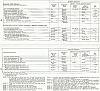
Click on the image for full sized pages 64-65
65